How to make a solar charger for your phone with your own hands. How to charge a mobile device faster.
Most modern gadgets (mobile phones, smartphones, music players, electronic books, etc.) support charging via the USB mini / micro jack. There may be several connection options:
- The device can be charged from a PC via a standard data cable. Usually it is a USB_AM — USB_BM_mini / micro cable. If the device requires more than 0.5 A to charge (this is the maximum USB 2.0 is capable of), then the charge time can be painfully long, down to infinity. The USB 3.0 port (such a blue one) already produces 0.9 A, but even this may not seem enough to anyone.
- Through the same data cable, your device can be charged from native a charger (mains or car), equipped with a 4-pin USB-AF socket, as on a computer. Of course, this is no longer a real USB port. The charger slot only gives out about 5 V between 1 and 4 pins of a 4-pin socket (plus on pin # 1, minus on pin # 4). Well, even between the different contacts of the socket can be installed all kinds of jumpers and resistors. What for? About this witchcraft will be discussed below.
- The gadget can be connected to an unauthorized or self-made charger, giving 5 volts. And here the most interesting begins ...
When you try to charge from someone else's charger with a USB output, your gadget may refuse to charge on the pretext that the charger does not seem to suit him. The answer is that many phones / smartphones “look” at how the Data + and Data- wires are disconnected, and if the gadget doesn’t like something, this memory will be rejected.
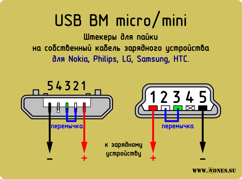
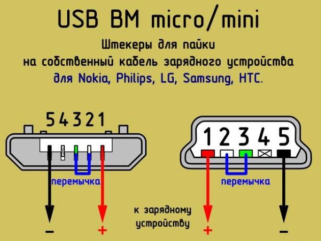
Nokia, Philips, LG, Samsung, HTC and many other phones recognize the charger only if the Data + and Data- pins (2nd and 3rd) are shorted. You can short-circuit them in the USB_AF of the charger and safely charge your phone via a standard data cable.
If the charger already has an output cord (instead of the output jack), and you need to solder the mini / micro USB plug to it, then do not forget to connect 2 and 3 pins in the mini / micro USB itself. At the same time, plus you solder to 1 contact, and minus to the 5th (last).
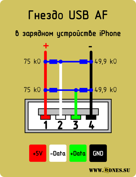
Have Iphone there are some occult requirements for switching the charger socket: Data + (2) and Data- (3) contacts must be connected to GND (4) contact through 49.9 kΩ resistors, and to + 5V contact through 75 kΩ resistors.
Motorola "Requires" a 200 kΩ resistor between the 4 and 5 pin contacts of a micro-BM USB connector. Without a resistor, the device is not charging until complete victory.

For charge Samsung galaxy A 200 kΩ resistor between 4 and 5 pins and a jumper between 2 and 3 pins must be installed in the micro-BM USB plug.

As a rule, a tablet requires a decent current (1 ÷ 1.5 amps) for charging, and the charge through the mini / micro USB port in many tablets is simply not provided by the manufacturer. After all, even USB 3.0 will not give more than 0.9 amps.
True, some models of tablets can be slowly and sadly charged in the off state.
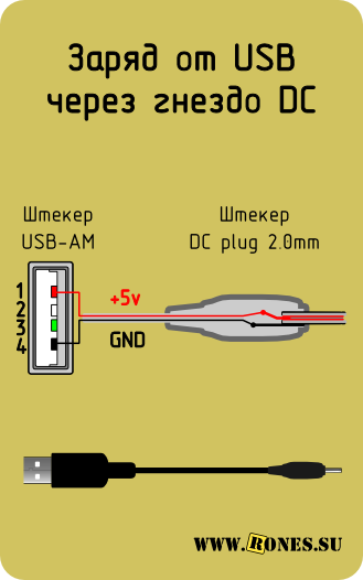
On YouTube, one guy offers to install in the 3Q tablet a jumper between the first pin of the mini / micro USB connector (this is +5 V) and the positive (central) contact of the round (coaxial) charging socket. Say, there is enough current from USB to this tablet, just the USB jack is not connected to the battery charge controller. After setting the jumper, the tablet is supposedly charging. In principle, this is the way out if the round charger socket itself is already broken.
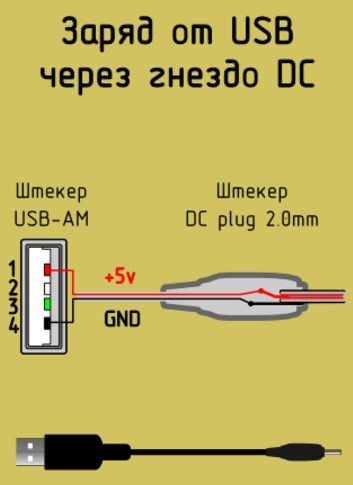
On the contrary, if the round socket is in order, but for some reason you want to take power to charge it from a USB computer or a charger with such a connector, then you can make this adapter:
Do-it-yourself solar USB charging for your phone is one of the most interesting and useful projects on. Making an improvised charger is not too difficult - the necessary components are not very expensive and easy to get. USB solar chargers are ideal for charging smaller devices, such as phones.
The weak point of all self-made solar charges are batteries. Most of them are built on the basis of standard nickel-metal hydride batteries - cheap, affordable and safe to use. But unfortunately, NiMH batteries have too low voltage and capacity so that they can be seriously considered as quality, the power consumption of which only grows every year.

For example, an iPhone 4 battery at 2000 mAh can still be fully recharged from self-made solar charging with two or four AA batteries, but the iPad 2 is equipped with a 6000 mAh battery, which is not so easy to recharge using a similar charger.

The solution to this problem is the replacement of nickel-metal hydride batteries for lithium.
From this manual you will learn how to do solar USB charging with a lithium battery with your own hands. First, in comparison with this self-made charger will cost you very cheap. Secondly, it is very easy to assemble it. And most importantly - this lithium USB charging is safe during operation.
Step 1: The necessary components to build a solar USB charging.

Electronic components:
- 5V or higher solar panel
- 3.7 V lithium-ion battery
- Lithium-ion battery charging controller
- USB dc boost circuit
- Connector 2.5 mm with panel mounting
- Connector 2.5 mm with wire
- Diode 1N4001
- The wire

Construction materials:
- Insulating tape
- Heat shrinkable tubing
- Double Sided Foam Tape
- Solder
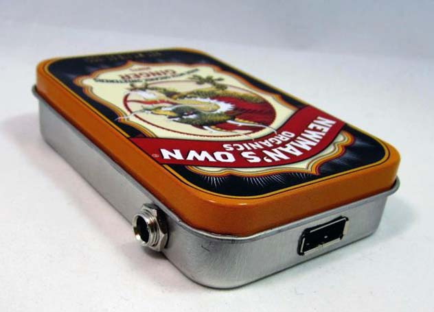
- Tin box (or other housing)

Instruments:
- Soldering iron
- Hot glue gun
- Drill
- Dremel (optional but desirable)
- Nippers
- Wire Stripper
- Friend help

This guide explains how to make a solar-powered phone charger. You can stop using solar batteries and limit yourself to making conventional USB charging on lithium-ion batteries.
Most of the components for this project can be purchased at online electronics stores, but it will not be so easy to find a USB dc circuit and charge controller for a lithium-ion battery. Later in this guide, I will tell you where you can get most of the necessary components and why each one is needed. Based on this, you decide which option is best for you.

Step 2: The Benefits of Lithium Battery Chargers

Maybe you can not guess, but most likely the lithium-ion battery is right now in your pocket or on the table, and maybe in your wallet or. Most modern electronic devices use lithium-ion batteries, characterized by high capacity and voltage. They can be recharged many times. The majority of AA batteries are nickel-metal hydride in chemical composition and cannot boast high technical characteristics.
From a chemical point of view, the difference between a standard nickel-metal hydride AA battery and a lithium-ion battery is in the chemical elements contained within the battery. If you look at the periodic table of the elements of Mendeleev, you will see that lithium is in the left corner next to the most chemically active elements. But nickel is located in the middle of the table next to the chemically inactive elements. Lithium has such a high chemical activity due to the fact that it has only one valence electron.

And precisely for this reason, lithium has many complaints - sometimes it can get out of control due to its high chemical activity. A few years ago, Sony, the leader in the production of laptop batteries, produced a batch of low-quality laptop batteries, some of which spontaneously ignited.
That is why when working with lithium-ion batteries, we must adhere to certain precautions - very accurately maintain the voltage during charging. This manual uses 3.7 V batteries that require a charging voltage of 4.2 V. If this voltage is exceeded or reduced, a chemical reaction can get out of control with all the ensuing consequences.
That is why it is necessary to exercise extreme caution when working with lithium batteries. If you handle them carefully, they are safe enough. But if you do unacceptable things with them, it can lead to big troubles. Therefore, they should be operated only strictly according to the instructions.
Step 3: Select the lithium-ion battery charge controller.
Due to the high chemical reactivity of lithium batteries, you must be one hundred percent sure that the charging voltage control circuit will not let you down.
Although you can make your own voltage control circuit, it is better to simply buy a ready-made circuit, in the performance of which you will be sure. There are several charge control schemes available.
Currently, Adafruit has released the second generation of charge controllers for lithium batteries with several available input voltage values. These are very good controllers, but they are too large. It is unlikely that they will be able to assemble a compact charger on their base.
On the Internet, you can buy small modules of charge controllers for lithium batteries, which are used in this guide. On the basis of these controllers, I also gathered many others. I like them for their compactness, simplicity and availability of LED indication of battery charge. As in the case of Adafruit, in the absence of the sun, the lithium battery can be charged via the USB port of the controller. The ability to charge via the USB port is an extremely useful option for any solar powered charger.
Regardless of which controller you choose, you need to know how it works and how to use it properly.
Step 4: USB port.

Through the USB port you can charge most modern devices. This is the standard worldwide. Why not just connect the USB port directly to the battery? Why do we need a special scheme for charging via USB?
The problem is that according to the USB standard, the voltage is 5 V, and the lithium-ion batteries that we will use in this project have a voltage of just 3.7 V. Therefore, we will have to use the USB boosting DC circuit, which increases the voltage to sufficient to charge various devices. In the majority of commercial and self-made USB charges, on the contrary, lowering circuits are used, since they are assembled on the basis of 6 and 9 V batteries. Charts with voltage drops are more complicated, therefore it is better not to use them in solar charging devices.

The scheme used in this manual was chosen as a result of long-term testing of various options. It is almost identical to the Minityboost Adafruit scheme, but it is cheaper.
Of course, you can buy an inexpensive USB charger online and disassemble it, but we need a circuit that converts 3 V (voltage of two AA batteries) to 5 V (voltage on USB). Disassembling normal or car USB charging will not do anything, since their circuits work to reduce the voltage, but on the contrary, we need to increase the voltage.
In addition, it should be noted that the Mintyboost scheme and the scheme used in the project are able to work with Apple gadgets, unlike most other USB charging devices. Apple devices check the information pins for USB to know where they are connected. If the Apple gadget determines that the information pins do not work, it will refuse to charge. Most other gadgets do not have this check. Believe me - I tried a lot of cheap charging schemes from eBay online auction - I couldn’t charge my iPhone from any of them. You do not want your self-made USB charging to charge Apple gadgets.
Step 5: Select the battery.
If you google a bit, you will find a huge variety of sizes, capacities, voltages and cost. At first, in all this diversity it will be easy to get confused.
For our charger, we will use a 3.7 V lithium polymer (Li-Po) battery, which is very similar to a battery for an iPod or mobile phone. Indeed, we only need a battery of 3.7 V, since the charging circuit is designed specifically for this voltage.
The fact that the battery should be equipped with built-in protection against overcharging and overdischarge is not even discussed. Usually this protection is called “PCB protection”. Search for these keywords on eBay online auction. She is just a small circuit board with a chip that protects the battery from overcharging and discharging.
When choosing a lithium-ion battery, look not only at its capacity, but also at its physical size, which mainly depends on your chosen case. I made the Altoids tin box as my case, so I was limited in battery selection. At first I thought to buy a 4400 mAh battery, but because of its large size, I had to confine myself to a 2000 mAh battery.
Step 6: Connect the solar battery.

If you are not going to make a charger with the possibility of recharging from the sun, you can skip this step.
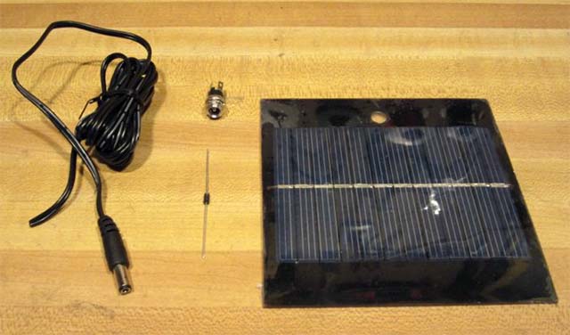
This manual uses a solar cell in a 5.5 V and 320 mA rigid plastic case. Any large solar cell will suit you. For a charger, it is best to choose a battery rated for 5-6 V.

Take the wire by the tip, divide it into two pieces and strip the ends slightly. The wire with a white stripe is negative, and the completely black wire is positive.

Solder the wires to the corresponding contacts on the back of the solar panel.
Cover the soldering points with electrical tape or hot glue. This will protect them and help reduce the load on the wires.
Step 7: Drill a tin box or case.

Since I used the Altoids tin box as a case, I had to work a little with a drill. In addition to the drill, we also need a tool such as a Dremel.
Before you start working with a tin box, put all the components into it to make sure in practice that it suits you. Think over how best to place the components in it, and then drill. Component locations can be marked with a marker.

After the designation of places can get to work.
You can output the USB port in several ways: make a small cut right at the top of the box or drill a hole of the appropriate size on the side of the box. I decided to make a hole on the side.

First attach the USB port to the box and mark its place. Drill two or more holes in the marked area with a drill.

Grind the hole with a Dremel. Be sure to follow safety precautions so as not to injure your fingers. Do not hold the box in your hands - hold it in a vice.
Drill a hole with a diameter of 2.5 mm for the USB port. If necessary, expand it with Dremel. If you do not plan to install a solar battery, then there is no need for a 2.5 mm hole!
Step 8: Connect the charging controller.
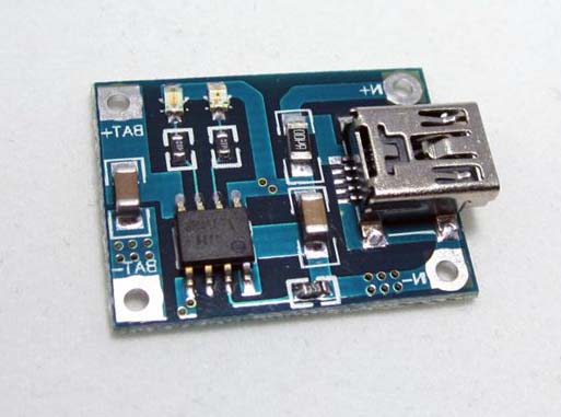
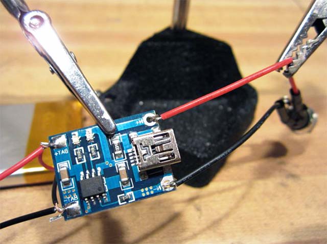
One of the reasons why I chose this compact charging controller is its high reliability. It has four pads: two in front of the mini-USB port, where constant voltage is applied (in our case from solar panels), and two in the back for the battery.

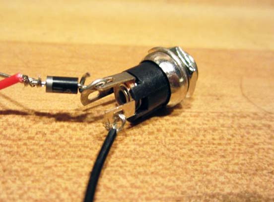
To connect the 2.5 mm jack to the charging controller, you need to solder two wiring and a diode from the jack to the controller. In addition, it is desirable to use shrinkable tubes.
Fix the 1N4001 diode, charging controller and 2.5 mm jack. Place the connector in front of you. If you look at it from left to right, the left contact will be negative, the middle one will be positive, and the right contact will not be used at all.
Solder one end of the wiring to the negative leg of the connector, and the other to the negative contact on the board. In addition, it is desirable to use shrinkable tubes.
Solder one more posting to the leg of the diode, next to which the label is applied. Solder it as close as possible to the base of the diode to save more free space. Solder the other side of the diode (without label) to the middle leg of the connector. Again, try to solder as close as possible to the base of the diode. And finally, solder the wiring to the positive contact on the board. In addition, it is desirable to use shrinkable tubes.
Step 9: Connect the battery and USB circuit.

At this stage, you only need to solder four additional contacts.

You need to connect the battery and USB circuit to the charge controller board.

First cut a few wires. Solder them to the positive and negative contacts on the USB circuit, which are located on the bottom side of the board.
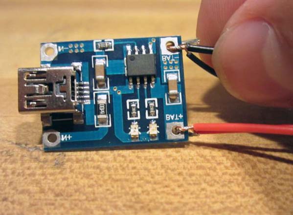
Then connect these wiring together with the wiring from the lithium-ion battery. Make sure you connect negative wiring together and connect positive wiring together. I remind you that the red wires are positive and the black ones are negative.

After twisting the wiring together, weld them to the battery contacts on the back of the charge controller board. Before soldering wiring, it is advisable to thread through the holes.
Now we can congratulate you - you have managed 100% of the electrical part of this project and you can relax a bit.

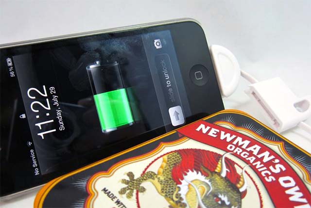
At this stage, a good idea would be to check the performance of the circuit. Since all electrical components are connected, everything should work. Try charging an iPod or any other gadget equipped with a USB port. The device will not charge if the battery is low or defective. In addition, place the charger in the sun and see if the battery will be charged from the solar battery — a small red LED on the charge controller board should come on. You can also charge the battery via a mini-USB cable.
Step 10: Electrical insulation of all components.

Before placing all electronic components in a tin box, we must be sure that it cannot cause a short circuit. If you have a plastic or wooden case, skip this step.
Apply several strips of electrical tape to the bottom and sides of the tin box. It is in these places will be a USB circuit and a charging controller. In the photos you can see that the charging controller I was left loose.
Try to insulate everything carefully so that a short circuit does not occur. Before applying hot glue or winding electrical tape, make sure that the solder is strong.
Step 11: Placement of electronic components in the housing.

Since the 2.5 mm connector must be fixed with bolts, place it first.


There was a switch on my USB side. If you have the same scheme, then first check whether the switch that is needed to enable and disable the "charging mode" is working.
Finally, you need to secure the battery. To this end, it is better not to use hot glue, but a few pieces of double-sided tape or tape.

Step 12: Operation of a self-made solar-powered charger.

In conclusion, let's talk about the proper operation of self-made USB charging.
You can charge the battery through the mini-USB port or from the sun. A red LED on the charge controller board indicates the charging process, and a blue one on a fully charged battery.
Problems with charging various devices via USB often arise when using non-standard chargers. In this case, charging is rather slow and not completely or completely absent.
It should be said that charging via USB is not possible with all mobile devices. They have this port only for data transmission, and a separate round jack is used for charging.
The output current in computer USB is no more than half an ampere for USB 2.0, and for USB 3.0 it is 0.9 A. In a series of devices this may not be enough for a normal charge.
It happens that you have a charger at your disposal, but it does not charge your gadget (this may be indicated by an inscription on the display or there will be no charge indication). Such a memory device is not supported by your device, and perhaps this is because a number of gadgets scans the presence of a certain voltage on pins 2 and 3 before starting the charging process. For other devices, the presence of a jumper between these pins, as well as their potential, may be important.
Thus, if the device does not support the proposed type of charger, the charging process will never begin.
In order for the device to start charging from the charger provided to it, it is necessary to provide the necessary voltages on USB 2 and 3. For different devices, these voltages may also differ.
For many devices it is required that pins 2 and 3 have a jumper or resistance element, the nominal of which is not more than 200 Ohms. Such changes can be made in the USB_AF socket, which is in your memory. Then charging will be possible to produce a standard Data-cable.
The Freelander Typhoon PD10 gadget requires the same wiring, but the charge voltage should be at 5.3 V.
If the charger does not have a USB_AF socket and the cord comes straight out of the charger, you can solder the mini-USB or micro-USB plugs to the cable. Connections must be made as shown in the following picture:
Various Apple products have the following connection option:

In the absence of an element of resistance with a nominal 200 kΩ on pins 4 and 5, Motorola devices cannot carry out a full charge.

To charge the Samsung Galaxy, you must have a jumper on pins 2 and 3, as well as a 200 kΩ resistance element on pins 4 and 5.

The full charge of the Samsung Galaxy Tab in a spare mode is recommended when using two resistors of 33 kΩ and 10 kΩ, as shown in the picture below:

A device such as the E-ten can be charged with any charger, but only if the pins 4 and 5 are connected by a jumper.

This scheme is implemented in the USB-OTG cable. But in this case, you must use an additional USB dad-dad adapter.

The universal Ginzzu GR-4415U memory and other similar devices have sockets with various connections of resistors for charging iPhone / Apple and Samsung / HTC devices. The pinout of these ports looks like this:

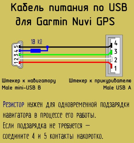
To charge your Garmin navigator, you need the same cable with a jumper on pins 4 and 5. But in this case, the device cannot be charged during operation. In order for the navigator to be recharged, it is necessary to replace the jumper with a 18 kΩ resistor.

Charging tablets usually requires 1-1.5 A, but as mentioned earlier, USB ports will not be able to charge them properly, since USB 3.0 will output a maximum of 900 mA.
In some models of tablets for charging there is a round coaxial jack. The plus pin of the mini-USB / micro-USB jack in this case does not have a connection to the battery charge controller. According to some users of such tablets, if you connect the plus from the USB jack to the plus coaxial jack with a jumper, then you can charge via USB.
Or you can make an adapter for connecting to a coaxial jack, as shown in the figure below:

Here are the jumper circuits with voltage and nominal resistors:
As a result, in order to charge various gadgets from non-native memory devices, you must make sure that charging produces a voltage of 5 V and a current of at least 500 mA, and make changes to the USB socket or plug according to the requirements of your device.
Most modern mobile phones, smartphones, tablets and other wearable gadgets support charging via the USB mini-USB or micro-USB jack. True to a single standard so far away, and each company is trying to make a pinout in its own way. Probably to buy a charger from her. Well at least the YUSB plug and socket was made standard, as well as the supply voltage of 5 volts. So having any charger adapter, you can theoretically charge any smartphone. How? and read on.

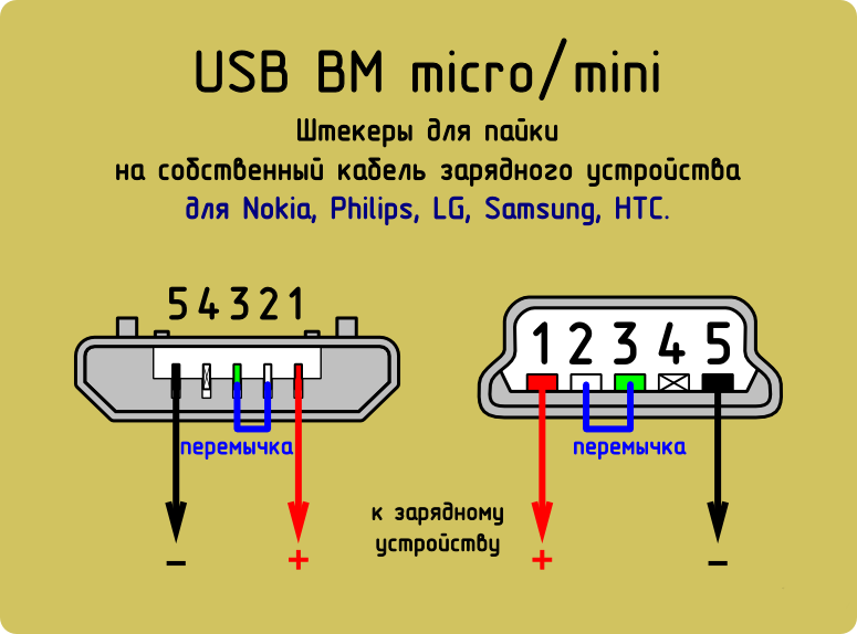
Pinout USB connectors for Nokia, Philips, LG, Samsung, HTC
Brands Nokia, Philips, LG, Samsung, HTC and many other phones recognize the charger only if the contacts Data + and Data- (2nd and 3rd) are shorted. You can short-circuit them in the USB_AF of the charger and safely charge your phone via a standard data cable.

Pinout USB connectors on the plug
If the charger already has an output cord (instead of an output jack), and you need to solder a mini-USB or micro-USB plug to it, then you do not need to connect 2 and 3 pins in the mini / micro USB itself. At the same time, plus you solder to 1 contact, and minus to the 5th (last).
Pinout USB connectors for Iphone
For iPhones, the Data + (2) and Data- (3) contacts must be connected to the GND (4) contact via 50 kΩ resistors, and to the + 5V contact through 75 kΩ resistors.

Pinout of Samsung Galaxy Charging Connector
To charge Samsung Galaxy, a 200 kΩ resistor between 4 and 5 pins and a jumper between 2 and 3 pins must be installed in the micro-BM USB plug.

Pinout USB connectors for Garmin navigator
A separate data cable is required to power or charge your Garmin navigator. Just to power the navigator through the cable you need to short-circuit 4 and 5 pins in the mini-USB plug. For recharging, you need to connect 4 and 5 contacts through an 18 kΩ resistor.
Charts for charging tablets
Virtually any tablet computer needs a large amount of current to charge - 2 times more than a smartphone, and the charge through the mini / micro USB port in many tablets is simply not provided by the manufacturer. After all, even USB 3.0 will not give more than 0.9 amps. Therefore, a separate nest is installed (often of a round type). But it can also be adapted for a powerful USB power source, if you solder such an adapter.
Pinout Charging Socket Tablet Samsung Galaxy Tab
To properly charge the tablet Samsung Galaxy Tab recommend a different circuit: two resistors: 33 kΩ between +5 and jumper D-D +; 10 kΩ between GND and D-D + jumper.

Pinout charging ports
Here are a few voltage circuits on the USB pins with indication of the resistors rating, which allow to receive these voltages. Where 200 ohm impedance is indicated, a jumper should be placed, the resistance of which should not exceed this value.
Charger Port Classification
- SDP (Standard Downstream Ports) - data exchange and charging, allows current up to 0.5 A.
- CDP (Charging Downstream Ports) - data exchange and charging, allows current up to 1.5 A; hardware identification of the type of port (enumeration) is made before the gadget connects data lines (D- and D +) to its USB transceiver.
- DCP (Dedicated Charging Ports) - only charging, allows current up to 1.5 A.
- ACA (Accessory Charger Adapter) - PD-OTG operation in Host mode is declared (with connection to PD peripherals - USB-Hub, mouse, keyboard, HDD and with the possibility of additional power), for some devices - with the ability to charge PD during OTG session .
How to remake the plug with your own hands
 Now you have a pinout scheme for all popular smartphones and tablets, so if you have the skill of working with a soldering iron, there will be no problems with remaking any standard USB connector to the type of device you need. Any standard charge that is based on using USB, involves the use of only two wires - this is + 5V and a common (minus) contact.
Just take any charging adapter 220V / 5V, cut off the YUSB connector from it. The cut end is completely free of the screen, while the other four wires are stripped and tinned. Now we take the cable with the USB connector of the desired type, after which we also cut off the excess from it and carry out the same procedure. It now remains just to solder the wires together according to the scheme, after which the connection is isolated each separately. The resulting case at the top is mated with tape or tape. You can pour hot melt - also a normal option.
The world of technology has finally united around a single charging standard after many years of proprietary adapters and power supplies. We already even see some hints on the new USB-C connector, which should replace the existing USB, as well as USB Micro-B, which Samsung once introduced to the Galaxy line. But before that, without taking Apple Lightning into account, the Micro USB connector destroyed the inclination of the entire industry to individual ports.
Ten years ago, you had to make sure that you had a suitable charge for each device. Today, you can charge your phone at a friend’s place, connect to any computer and upload photos from a digital camera directly to the TV using one wire. But another problem arises - USB power. Not all USB chargers, connectors and cables are the same. You may have noticed that some USB connectors are more powerful than others. On some desktops, even when they are turned on, you can safely charge your smartphone via USB in a fairly short time.

Now there are four types of USB - USB 1.0, 2.0, 3.0 and 3.1, not counting the new USB-C connector. In addition, for most USB networks, there are two types of devices - the “host” and the peripheral device. In most cases, the PC is the master, and the smartphone, tablet or camera is the device. Energy always flows from the host to the device, but data can flow in both directions.
And now the numbers - the USB connector has four pins, and the USB cable has four wires. Internal data transfer contacts (D + and D-) and external pins provide 5V power. In terms of actual current settings (milliamperes or mA), there are three types of USB ports — the standard output port, the charging output port, and the dedicated charging port. The first two can be found in the computer, and the third is found in the "wall" charges.
In USB 1.0 and 2.0, the standard output port can output up to 500 mA (0.5 A), in USB 3.0, the value rises to 900 mA (0.9 A). The output charging port and dedicated charging port provide up to 1500 mA (1.5A). USB 3.1 can have bandwidth up to 10 Gbps in SuperSpeed mode, which is roughly equivalent to the first-generation Thunderbolt. It also supports current strengths of 1.5A and 3A.
The USB-C connector will be completely different. Firstly, it is universal. Secondly, it provides twice the bandwidth compared to USB 3.0 and can output more power. Apple used USB-C in its new MacBook, like Google in the latest Chromebook Pixel. But there are also older connectors that support standard 3.1.
USB has the ability to charge in sleep mode when the ports remain active when the computer is turned off. But besides stationary PCs, some laptops are capable of this.

There are many variations between regular 500 mA USB ports and dedicated charging connectors, which range up to 3000 mA. This leads to a rather important question: if you take a smartphone that comes with a charger for a 900 mA outlet and plug it in via a charger for a 2100 mA iPad, will there be a problem?
In general, no. You can connect any USB device through any USB cable to any USB connector and nothing will explode, and a more powerful charger will even speed up battery charging.
A more specific answer is that a lot depends on the age of the device. Back in 2007, USB Implementers Forum introduced the Battery Charging Specification with standardization of faster charging methods. Shortly thereafter, USB devices began to implement these functions.
If you have a modern device, then almost every smartphone, tablet and camera can be connected to a high-current connector and enjoy the benefits of fast charging. However, if you use legacy devices, they probably will not work with the Battery Charging Specification. They can only work with old USB ports 1.0 and 2.0 (usually 500 mA). In some particularly severe cases, devices can be charged using a computer only with certain drivers.
But there are a few more things that are useful to know. While computers can have two kinds of USB connectors — a standard output and a charging port, manufacturers rarely label them as such. As a result, the device can be charged only from one of them. For the same reason, some external devices - hard drives and optical drives may require more power than the USB port can provide, so they have a Y-like cable or an optional AC adapter.
In any case, USB made charging gadgets much easier. And if the new USB-C connector provides all the promised functionality, everything will become even better, and we will permanently get rid of problems with incorrect connection.