Arduino port expansion for buttons. How to increase the number of digital pins on Arduino using a port expander. Selecting an expander module for Arduino
Thirteen digital lines and six analog inputs are all that Arduino has to offer as input/output facilities. But in some cases (especially in projects with a large number of peripheral devices) such a set of port lines is not enough.
In this regard, the question arises about the feasibility of expanding the number of input/output lines. This material will show an example of such an expansion using the MCP23017 chip.
You may know that the 6 analog pins can also be used as digital I/O pins this way:
Analog input 0 = line 14
Analog input 1 = line 15
Analog input 2 = line 16
Analogue input 3 = line 17
Analog input 4 = line 18
Analogue input 5 = line 19
So we can actually refer to analog input 5 as a digital line like this: digitalWrite(19,HIGH). Such a command will write a logical one to port 19, that is, analog line 5.
Technically we can use TX/RX serial port lines. But in some cases this is extremely difficult to do, especially when the code uses functions like Serial.begin(), which are necessary for the operation of the serial port. Thus, the total number of contacts available to the user will still be 17. But is it possible with seventeen pins to control a large number of LEDs or servomotors? In this case, it is better to use special external microcircuits. Often a shift register like the 74HC595 is used for these purposes. But it requires three additional lines for control and does not allow you to “expand” all the lines at the same time. Display drivers such as the MAX7219 also actually “expand” the number of pins. But the MAX7219 is an expensive chip. Therefore, it is cheaper and more rational to take the MCP23017 port expander chip. This chip is designed for 16 lines, has a wide operating voltage range from 1.8 to 5.5 V and is controlled via the I2C interface.
The MCP23017 will use 2 Arduino pins and give 16 I/O lines. So technically you can use 8 pieces of MCP23017 to expand one 16 pin Arduino to 16 x 8 = 128 pins. Arduino has a library for the I2C bus called Wire.h, so interfacing with the MCP23017 will be very simple. Below is the connection diagram between Arduino and MCP23017.

#include "Wire.h" void setup() ( Wire.begin(); // activate the I2C bus // set the lines to the output Wire.beginTransmission(0x20); Wire.write(0x00); // IODIRA register Wire.write (0x00); // set all lines of port A to output Wire.endTransmission(); ) void loop() ( Wire.beginTransmission(0x20); Wire.write(0x12); // address bank A Wire.write((byte )0xAA); // sent value - all lines in log. 1 Wire.endTransmission(); Wire.beginTransmission(0x20); // address bank A Wire.write(( byte)0x55); // sent value - all lines in log. 1 Wire.endTransmission();
One of the key advantages of the Arduino platform is its popularity. The popular platform is actively supported by manufacturers of electronic devices, producing special versions of various boards that expand the basic functionality of the controller. Such boards, quite logically called expansion boards (another name: arduino shield, shield), are used to perform a wide variety of tasks and can significantly simplify the life of an arduino operator. In this article, we will learn what an Arduino expansion board is and how it can be used to work with a variety of Arduino devices: motors (motor driver shields), LCD screens (LCD shields), SD cards (data logger), sensors (sensor shield ) and many others.
Let's first understand the terms. An Arduino expansion board is a complete device designed to perform certain functions and is connected to the main controller using standard connectors. Another popular name for the expansion board is the English-language Arduino shield or simply shield. All the necessary electronic components are installed on the expansion board, and interaction with the microcontroller and other elements of the main board occurs through standard Arduino pins. Most often, power to the shield is also supplied from the main arduino board, although in many cases it is possible to power it from other sources. In any shield there are several free pins that you can use at your discretion by connecting any other components to them.
The English word Shield is translated as shield, screen, screen. In our context, it should be understood as something that covers the controller board, creating an additional layer of the device, a screen behind which various elements are hidden.
Why do we need arduino shields?

Everything is very simple: 1) so that we save time, and 2) someone can make money from this. Why waste time designing, placing, soldering and debugging something that you can take already assembled and start using right away? Well-designed expansion cards assembled on high-quality equipment are usually more reliable and take up less space in the final device. This does not mean that you need to completely abandon self-assembly and you do not need to understand the principle of operation of certain elements. After all, a real engineer always tries to understand how what he uses works. But we will be able to make more complex devices if we do not reinvent the wheel every time, but focus our attention on what few people have solved before.
Naturally, you have to pay for opportunities. Almost always, the cost of the final shield will be higher than the price of individual components; you can always make a similar option cheaper. But here it’s up to you to decide how critical the time or money spent is for you. Taking into account all possible assistance from Chinese industry, the cost of boards is constantly decreasing, so most often the choice is made in favor of using ready-made devices.
The most popular examples of shields are expansion boards for working with sensors, motors, LCD screens, SD cards, network and GPS shields, shields with built-in relays for connecting to the load.
Connecting Arduino Shields
To connect the shield, you just need to carefully “put” it on the main board. Typically, the contacts of the comb type shield (male) are easily inserted into the connectors of the Arduino board. In some cases, it is necessary to carefully adjust the pins if the board itself is not properly soldered. The main thing here is to act carefully and not use excessive force.
As a rule, a shield is intended for a very specific version of the controller, although, for example, many shields for Arduino Uno work quite well with Arduino Mega boards. The pinout on the mega is made in such a way that the first 14 digital pins and the pins on the opposite side of the board coincide with the pinout on the UNO, so an Arduino shield can easily be inserted into it.
Arduino Shield Programming
Programming a circuit with an expansion board is no different from regular Arduino programming, because from the point of view of the controller, we simply connected our devices to its regular pins. In the sketch you need to indicate those pins that are connected in the shield to the corresponding contacts on the board. As a rule, the manufacturer indicates the correspondence of the pins on the shield itself or in a separate connection instruction. If you download the sketches recommended by the board manufacturer itself, then you won’t even need to do this.
Reading or writing shield signals is also done in the usual way: using the functions , and other commands familiar to any Arduino user. In some cases, collisions are possible when you are accustomed to a particular connection scheme, and the manufacturer has chosen a different one (for example, you pulled the button to the ground, and on the shield to the power supply). Here you just need to be careful.
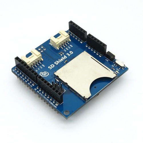
As a rule, this expansion board comes in Arduino kits and therefore it is with it that Arduino engineers encounter it most often. The shield is quite simple - its main task is to provide more convenient options for connecting to the Arduino board. This is done through additional power and ground connectors located on the board to each of the analog and digital pins. Also on the board you can find connectors for connecting an external power source (you need to install jumpers to switch), an LED and a restart button. Shield options and examples of use can be found in the illustrations.


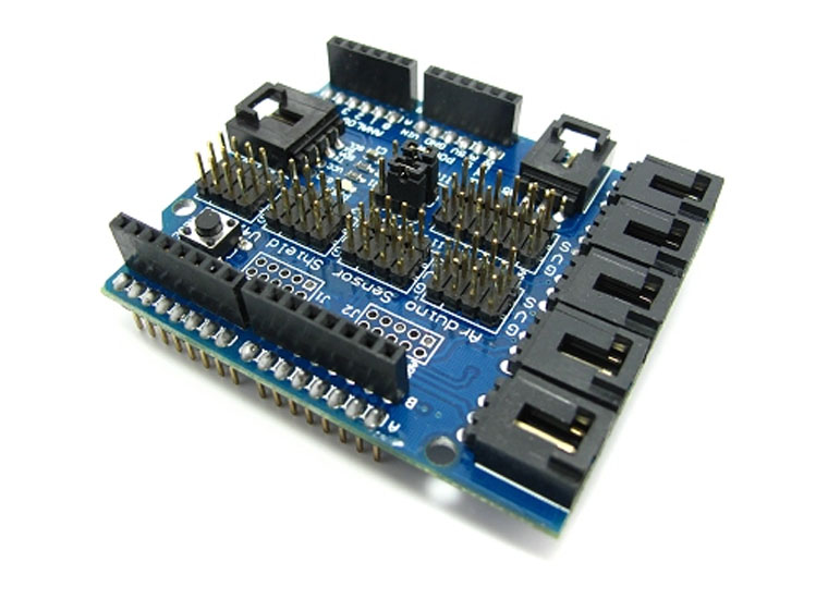

There are several versions of the touch expansion board. They all differ in the number and type of connectors. The most popular versions today are Sensor Shield v4 and v5.
This Arduino shield is very important in robotic projects, because... allows you to connect regular and servo motors to the Arduino board at once. The main task of the shield is to provide control of devices that consume a current that is high enough for a regular Arduino board. An additional feature of the board is the function of controlling motor power (using PWM) and changing the direction of rotation. There are many types of motor shield boards. Common to all of them is the presence in the circuit of a powerful transistor through which an external load is connected, heat-sinking elements (usually a radiator), a circuit for connecting external power, connectors for connecting motors and a pin for connecting to the Arduino.


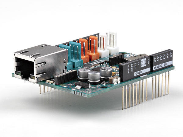
Organizing work with the network is one of the most important tasks in modern projects. A corresponding expansion card is available for connecting to a local network via Ethernet.


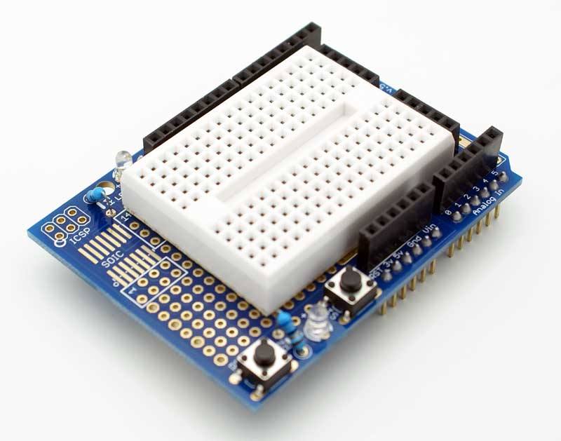
Expansion boards for prototyping
These boards are quite simple - they have contact pads for mounting elements, a reset button, and the ability to connect external power. The purpose of these shields is to increase the compactness of the device, when all the necessary components are located immediately above the main board.


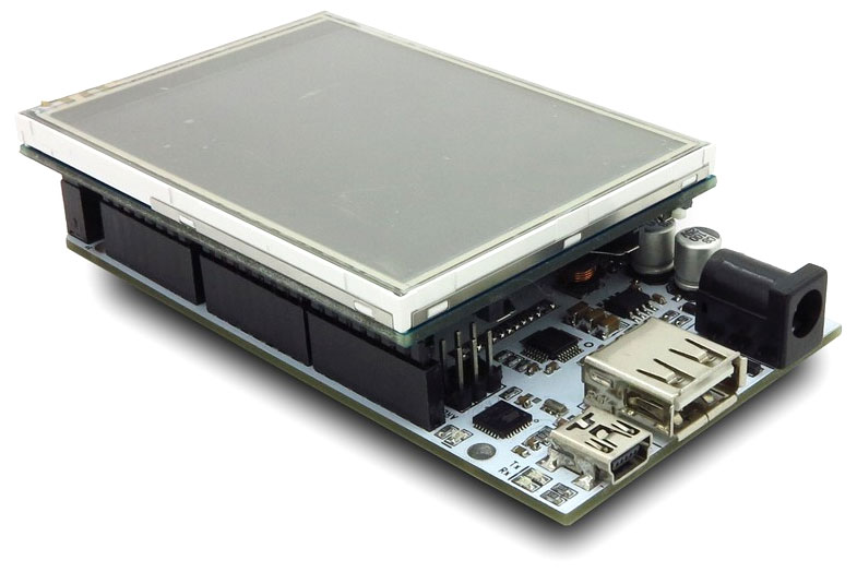
Arduino LCD shield and tft shield
This type of shield is used to work with LCD screens in Arduino. As you know, connecting even the simplest 2-line text screen is far from a trivial task: you need to correctly connect 6 screen contacts at once, not counting the power supply. It is much easier to insert the finished module into the Arduino board and simply upload the corresponding sketch. In the popular LCD Keypad Shield, from 4 to 8 buttons are immediately installed on the board, which allows you to immediately organize an external interface for the user of the device. TFT Shield also helps


Arduino Data Logger Shield
Another task that is quite difficult to implement independently in your products is saving data received from sensors with a time reference. The finished shield allows you not only to save data and get time from the built-in clock, but also to connect sensors in a convenient form by soldering or on a circuit board.


Brief summary
In this article, we looked at only a small part of the huge range of various devices that expand the functionality of Arduino. Expansion cards allow you to focus on the most important thing - the logic of your program. The creators of the shields have provided for correct and reliable installation and the necessary power supply. All that remains for you is to find the required board using the treasured English word shield, connect it to the Arduino and upload the sketch. Typically, any shield programming consists of performing simple actions to rename the internal variables of a ready-made program. As a result, we get ease of use and connection, as well as speed of assembly of finished devices or prototypes.
The disadvantage of using expansion cards is their cost and possible loss of efficiency due to the universality of shields, which lies in their nature. For your narrow task or end device, all shield functions may not be needed. In this case, you should use the shield only at the stage of prototyping and testing, and when creating the final version of your device, think about replacing it with a design with your own circuit and type of layout. It's up to you to decide, you have all the opportunities to make the right choice.
Everyone loves inexpensive Arduino boards, but so often a project just needs one or two free ports! And sometimes there are enough ports, but you don’t want to pull a bunch of wires to another part of the structure. Let's say you need to place several buttons and LEDs on the front panel of the device. It’s more reliable and easier to connect them to the main board with just two data bus wires, rather than a cable or harness, isn’t it?
Various Arduino port expanders are designed for such situations.
Typically, microcontroller pins implement several different functions, so there are different expanders:
- Standard GPIO port expander
- PWM output expander
- Analog input expanders – multiplexers and external ADCs
Separately, it is worth mentioning digital-to-analog converters (DACs) and address space expanders of the I2C bus. These devices do not directly duplicate the functions of ports, but expand the capabilities of microcontrollers.
In the first article of the series, we will talk about the simplest and most useful expanders that work as digital I/O ports. These are microcircuits and . They are designed and work absolutely identically, and differ only in the number of ports.
Selecting an expander module for Arduino
The most popular and inexpensive module is made on the PCF8574 chip (Fig. 1)
Rice. 1. Popular PCF8574 port expander module
Advantages:
- Low price.
- Modules can be connected in a chain by simply inserting the plugs of one module into the sockets of the previous one. Don't forget to set jumpers to different module addresses!
Flaws:
- It cannot be inserted directly into a breadboard (I recommend soldering the port connector to the reverse side).
- A total of eight ports in one module.
If you are in the mood for more serious projects, order a 16-bit PCF8575 module on Aliexpress. I strongly recommend the module shown in Fig. 2.
Rice. 2. PCF8575 Port Expander Module
Advantages:
- Twice as many ports.
- Built-in 3.3 volt power supply, can power other modules.
- Built-in logic level matching for the I2C bus at different supply voltages.
- Convenient format for prototyping board.
Flaws:
- Higher price.
Operating principle of the PCF8574/PCF8575 GPIO port expander
Data exchange occurs via the I2C bus. The connection to the Arduino board requires only four wires, including power. The expander address is set by three jumpers on inputs A0...A2, so you can simultaneously connect eight identical chips to the bus and get a maximum of 8*8=64 additional ports with PCF8574 or 8*16=128 with PCF8575 chip.
To output data to the port, write a data byte to the module address on the I2C bus. To read data from a port, read a byte at the same address. A byte is always written and read as a whole; individual bits are handled programmatically.
The outputs of the microcircuit are also inputs, and there is no service register that determines the purpose of the output. There is only a latch register into which the output byte is written. How is this possible?
The ports operate in a similar open collector fashion and are equipped with internal pull-up resistors. If a logical zero is written to the output, then the output transistor opens, which forcibly pulls the output to ground. Reading from such a port will always return zero.
Be careful when applying direct supply voltage to a pin that is low or when current is exceeded. 50 mA you will ruin the chip!
To use a port as an input, write a one to it. In this case, the internal transistor will be turned off, and the reading result will be determined by the external logic level applied to the pin. The free pin is connected to the power supply by a built-in resistor.
In order to simultaneously use some of the ports as inputs, and some as outputs, before each write of a byte of data to the expander, it is necessary to apply a mask of ones to those bits that correspond to the inputs using the “logical OR” operation. That's all)))
Interrupt generation
PCF857* Port Expanders Generate an Interrupt Pulse low level at the INT output for any change in the input signal at any input of the microcircuit. This is convenient if the expander serves a keypad. But you must determine in the interrupt handler yourself which button was pressed or released. The interrupt generator is equipped with a contact bounce suppression filter.
Example 1: Using the PCF8574 module
Let's assemble a simple circuit of four LEDs, a PCF8574 module and an Arduino board (Fig. 3 and 4). With this connection scheme, we don’t even need quenching resistors for the LEDs. Current flows through the LED and a built-in resistor connected to the power rail.
Rice. 3. PCF8574 module connection diagram
Rice. 4. Circuit layout with PCF8574 module
Copy and write sketch 1 to the Arduino board:
A high level is initially written to all ports of the chip, so ports P0...P3 can act as inputs.
The levels at the port pins are read every 500 ms and the reading result is displayed on the monitor. If you connect one of the inputs P0...P3 to a common wire, a zero appears in its bit. Then the read value is shifted to the left by four bits, the result is output to the port and one of the LEDs goes out. For example, if a zero is read at pin P0, the LED connected to pin P4 will turn off.
Please note that before each write to the expander we must apply a bitmask of ones to all bits that should be inputs: dataSend |= B00001111;
The routines for working with the I2C bus are extremely simplified; no errors are processed.
Advice: To find and check the module address on the I2C bus, you can use . It displays in the terminal the addresses of all devices that respond to a bus request.
Example 2: Using the PCF8575 module
The peculiarity of the PCF8575 module is that it has 16 ports, so it always write two bytes and read two bytes. This rule must be followed even if the second byte is not needed.
Let's change the diagram a little. We will connect the LEDs to ports P10…P13, and we will connect ports P00…P03 with a jumper to the common wire (Fig. 5 and 6).
Rice. 5. PCF8575 module connection diagram
Rice. 6. Circuit layout with PCF8575 module
In sketch 2, 1s are first written to all ports, then their status is read every 500 ms. The read routine returns a 16-bit word, which is divided into bytes. The contents of the low byte (pins P00...P07) are copied to the high byte and uploaded back to the module. If you connect one of the pins P00...P03 to the common wire, one of the LEDs connected to P10...P13 will go out.
// Library for working with I2C #include
Arduino library for PCF8574/PCF8575
The library can be downloaded from GitHub. But, as you can see, working with port expanders is very simple and you can easily do without a special library.
Description of Expander Shield
Expander Shield is an original additional module designed to increase the number of input/output ports of microcontrollers based on the Arduino platform, as well as other microcontrollers, using port expanders with an SPI or I2C interface.

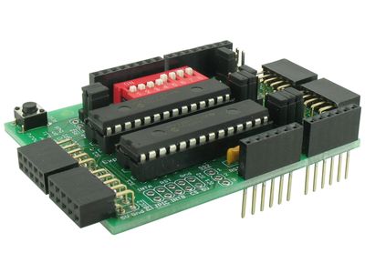
The main elements of the Expander Shield additional module are two MCP23S17 or MCP23017 microcircuits (two 16-bit I/O port expanders with SPI or I2C interface, respectively), which allow you to add four 8-bit I/O ports, that is, 32 additional “legs”.
Equipment
The Expander Shield module is supplied either as an assembled SPI or I2C version (with associated chips), or as a kit without chips, which can be purchased separately.
The module terminals may be equipped with transport locks, which must be removed before starting work.
Expander Shield SPI 1100 rub. 850 rub. Add to cart
order form.
ExpanderShield to SPI bus (with MCP23S17 chips).
Expander Shield I2C 1100 rub. 850 rub. Add to cart
Attention! You have JavaScript disabled. Normal operation of the ordering system and shopping cart is not possible. If for some reason you cannot enable JavaScript, simply list the items you are ordering on the order form.
ExpanderShield to I2C bus (with MCP23017 chips).

Specifications
Here are the most important functional features of the Expander Shield module.
- convenient module operating mode switch depending on the type of port expander chips currently installed;
- for each of the two used 16-bit I/O port expander chips, a three-bit address on the bus is set using jumpers, which allows you to place up to 8 such chips on one bus;
- the ability to use a jumper to select the number of the corresponding Freeduino/Arduino microcontroller output (digital pin 8, 9 or 10) for the CS signal of the SPI bus;
- the module uses “pass-through” connectors, allowing you to dock several modules without shifting relative to the Arduino board;
- microcircuit signals are output to four PBD-10R connectors with additional ground and +5V contacts;
- the ability to select a separate or joint hardware reset (RESET button) of the 16-bit I/O port expander chips and the Freeduino/Arduino microcontroller using jumpers;
- additional JPIC connector with interrupt pins (INTA, INTB), hardware reset (RST) and chip select (CS);
Other characteristics of the module are determined primarily by the characteristics of the MCP23S17/MCP23017 microcircuits, the technical description of which is available in the manufacturer’s documentation.
In addition, before starting to work with the additional Expander Shield module, we recommend that you familiarize yourself with its circuit diagram.
Operating modes
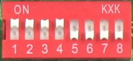
The Expander Shield operating mode is selected using a DIP switch and jumpers.
Interface selection and I2C bus pull-up control
Using a DIP switch, you select either SPI mode (by turning on contact group 1-4) for MCP23S17 microcircuits, or I2C mode (by turning on contact group 5-6) for MCP23017 microcircuits. Also, in I2C mode, using pins 7 and 8, if necessary, the I2C bus is pulled through current-limiting resistors to the +5V power bus. Typically, pull-up resistors should be connected if there is only one device on the I2C bus. If there are several devices, then resistors are connected only for one of the devices.
Simultaneous activation of the SPI and I2C bus, as well as the SPI bus and 7, 8 pin group not allowed.


The combined operating mode, when one of the two microcircuits in one Expander Shield module operates via the SPI interface (MCP23S17), and the other via the I2C interface (MCP23017), is impossible.
If you need to organize work simultaneously via SPI and I2C interfaces, you must use two (several) additional Expander Shield modules with the corresponding switch positions.
Selecting the pin number to control the CS signal of the SPI bus
For the SPI bus, you need to select the Freeduino/Arduino microcontroller pin used as the CS signal. Typically, pin 10 is used, which corresponds to the leftmost jumper position on the SS1 connector. By moving the jumper to one of the other two positions, it is possible to select pins 9 and 8, respectively.

Selecting the address of microcircuits on the bus
The lowest three bits of the address of the MCP23S17/MCP23017 microcircuits are selected using jumpers on the IC1_addr/IC2_addr connectors by pulling bits 0, 1, 2 to ground (Gnd) or +5V (5V).
The address of each chip must be unique.
Thus, up to 8 microcircuits can be placed on one bus (by combining, for example, 4 Expander Shields).

Selecting the hardware reset operating mode (RESET button)
It is possible to organize one of a number of operating modes of the RESET button
- The RESET button resets Freeduino/Arduino and MCP23S17/MCP23017 chips
- The RESET button only resets the Freeduino/Arduino
- The RESET button resets only MCP23S17/MCP23017 chips
The corresponding jumper positions on the JRS connector (from left to right) are shown below.

Library MCP23xxx
To simplify work with this and a number of other modules, the MCP23xxx library has been developed, which provides a simple interface to the functionality of the MCP23xxx series microcircuits. The library is available for free download: The library is compatible with Arduino software version 1.0.5 (compatibility with later versions is also expected).
In fact, this is a set of two libraries: MCP23xxx and LiquidCrystal_MCP23x17.
The installation of libraries is described in more detail in the section connecting libraries. The directory structure of the libraries folder after installation should be like this:
/libraries/LiquidCrystal_MCP23x17
/libraries/MCP23xxx
The MCP23xxx library implements class templates that organize work with the MCP23017, MCP23S17, MCP23008 and MCP23S08 port expanders. The LiquidCrystal_MCP23x17 library is a modified standard LiquidCrystal library that supports the Russian language and works through a port expander.
The library comes with examples that explain how to work with it. The previous version of the library is also available for download:
Let's look at an example of working with a module for the I2C bus:
//In the example, the state of the pins of the 1st chip is read, and the same values are set on the 2nd
//For the I2C version, connect Wire.h:
#include
//connect the library
#include
//Create two objects of the CMCP23017 class, but do not initialize them, because I2C bus is not ready
CMCP23017 mcp23_1;
CMCP23017 mcp23_2;
void setup()
{
//Initialize the I2C bus...
Wire.begin();
//... and MCP23* objects with addresses 0 and 1
mcp23_1.init(0);
mcp23_2.init(1);
//All pins of the 1st chip must be made inputs, and the 2nd ones - outputs
//This can be done in a loop
for (int i= 0 ; i<
16
;
i++
)
{
mcp23_1.pinMode (i, INPUT) ;
mcp23_2.pinMode (i, OUTPUT) ;
}
//or at one time, by calling the pinMode16 method
//mcp23_1.pinMode16(0x0ffff);
//mcp23_2.pinMode16(0x00000);
}
void loop()
{
//You can read all the inputs of the 1st chip and set the same on the 2nd in a loop
for (int i= 0 ; i<
16
;
i++
)
{
mcp23_2.digitalWrite (i, mcp23_1.digitalRead (i) ) ;
}
//or at a time, using the digitalRead16 and digitalWrite16 methods
//mcp23_2.digitalWrite16(mcp23_1.digitalRead16());
}
As I already did, I ordered three more or less non-overlapping sets of sensors for Arduino. In both sets, I received the 74HC595 microcircuit, which remained in the box for the time being. For the time being, I didn’t even know what kind of microcircuit it was, or how this black cockroach was even labeled.
But dark days came when I couldn't get enough of the Arduino Nano's output signals while I was building a device to test stepper motors. (TODO: insert a link to the article about the SD tester when ready). As a result, my device for testing stepper motors turned out to be quite complex - a two-line 1602 display with a menu system controlled by a full-function 4x4 keyboard, 3 digital digits for setting the microstepping value of the stepper motor, Step and Dir signals for the stepper motor, etc. It would seem that it's time to migrate to another version of Arduino. But my natural laziness opposed this migration. And the lazy head began to look for a solution.
It was decided to look for a solution based on what already exists. While sorting through scarves and parts from the kits, I noticed a 16-pin black “beetle”. First in one set, then in another. I decided to ask what kind of part this was and why it was added to the sets. I don’t understand why they put it in kits, but I found the chip itself on the NXP website.
It turned out that this is a rather interesting microcircuit - a shift register with a serial input and parallel output.
(from datasheet)
Description of pins
| Contact | Name | Description and connection |
|---|---|---|
| 10 | ~MR | Master Reset- reset, active level low. Ideally, it would be a good idea to make a reset circuit that first drives this input low and then drives it to a single state. But you don’t have to mess around and connect it to +5V. In this case, the output before the first record will contain random values |
| 13 | ~OE | Output Enable- output resolution, active level low. When 0 is applied, the contents of the register are supplied to the outputs; when 1 is applied, the outputs are turned off and transferred to the Z-state, which allows different devices to use one bus alternately. Connect to ground if you do not need to control the state of the outputs |
| 14 | D.S. | Serial Data In- serial input. This input must be set to the input signal value before the SHCP shift clock is applied. |
| 11 | SHCP | Shift Register Input clock- clock input of the shift register. To move a bit into a register, a transition from 0 to 1 must be applied. When to return to 0 is at your discretion. You can do it right away, you can do it just before pushing it in. In the first case, we can assume that switching occurs along the edge of the direct signal, in the second - along the decline of the inverse signal. See also performance notes below. Also, upon arrival of this signal, the value of the serial output Q7/S changes |
| 12 | STCP | Storage Register Clock Input- clock input of the latch register. At the edge of this pulse, the value is transferred from the shift register to the parallel outputs Q0-Q7 |
| 9 | Q7S | Serial Data Output- serial output. The value of the most significant bit of the shift register is displayed on it. This output can be used to scale the shift register to 16-bit, 24-bit, etc. scheme |
| 15, 1-7 | Q0, Q1-7 | Latch register outputs. The signal to them is transferred from the internal shift register upon arrival of the STCP signal |
| 8 | GND | Nutrition- common wire |
| 16 | VCC | Nutrition - + |
Nutrition
The HC version of the microcircuit requires from 2V to 6V power supply, the HCT version (TTL-compatible) - from 4.5V to 5.5V. HCT - TTL - is it still used? Arduino seems to be CMOS itself, so HCT is not needed, but if you need to coordinate the levels with external TTL consumers, then you can power the HC from 3.3V, then the signal levels will be compatible with TTL. In general, both HC and HCT should work with a 5-volt Arduino. This is what they write on the Internet.What is more important are the blocking capacitors. Without them, the circuit may not work as intended, and moreover, it may be unpredictable. Theoretically, a 0.1 µF capacitor should be installed in the power supply circuit of each case. I calculated this capacity value as an average from the Internet. My scheme worked just fine without him. To clarify, I went into the circuit designer’s bible to clarify - Hill and Horowitz, “The Art of Circuit Design” is almost like “The Art of Programming” by Donald Knutt, but only for hardware people (by the way, Hill and Horowitz are much closer to the people, Knutt through - he's being too clever) - but there they seem to call blocking capacitors the decoupling capacitors at the inputs. It’s a pity, it’s a good book, but it’s already very behind the times. I have the second or third Russian edition of the late 90s or early 0s, the original is most likely still 10 years older. On the third, pink volume, I found a sticker - “14 rubles” - how cheap everything was then, by modern standards. But only 15 years or a little more have passed. The nostalgia was overwhelming.
Performance
In the title of the datasheet 74HC595 they write that it operates at 100 MHz. A quick look at the datasheet graphs and tables says that the longest timings in the temperature range from -40C to +85C with a 4.5V power supply are 10-20ns (100-50MHz). With the frequencies at which Arduino operates, you don’t need to know anything else. It is only possible that the standard library digitalRead/digitalWrite are huge brakes due to various checks, and they can (and should) be rewritten as a faster version. I have plans to dig into this and write in more detail, but for now I don’t have a particular need.The performance of the Arduino Nano and the Arduino library in terms of the speed of switching outputs and processing inputs, according to my observations, is somewhere in the middle from a few kilohertz to tens of kilohertz. So, in my opinion, when writing code to control the 74HC595 shift register, there is no need to worry about any delays in setting the control signals.
Another thing is that for an 8-bit serial expander, you should divide the maximum output switching frequency available on Arduino - set DS, set SHCP to 1, reset SHCP (to 0) - 8 times, and set/reset STCP. Total, at a glance, 3 * 8 + 2 = 26 digitalWrite operations. In total, it turns out to be about 25 times slower than the Arduino itself can do.
When scaling to 16, 24 or 32 outputs, the slowdown will be approximately 3*16 + 2 = 50, 3*24 + 2 = 74 and 3*32 + 2 = 98 times, respectively.
Obviously, such a 74HC595 shift register expander is not suitable for controlling something really fast, but in some applications it is quite suitable for setting rarely changing static signals. So, for example, I used such an expander to set a 3-bit microstep mode to set the microstep mode for the DRV8825 stepper motor driver in a tester for stepper motors. By the way, this has not yet been particularly useful to me - steppers from dot matrix printers work terribly in microstepping mode, at least under the control of the DRV8825 driver - for example, in microstepping mode 1/2 half of the step is somehow sluggish and unsure, only the second half is upbeat and powerful. Therefore, when using a microstep, at the slightest effort on the stepper motor axis, it began to skip the first half steps. After that, I somehow did not explore the remaining microstepping modes on the existing printer SDs.
Scaling
The Arduino output expander based on the 74HC595 can be quite simply converted from the 8-bit version into a circuit of any capacity. To do this, the serial output of the low register Q7S must be connected to the DS input of the higher one, and the SHCP and STCP lines must be connected in parallel. Well, depending on the adopted circuitry and software solution, you need to choose how to connect the ~MR and ~OE lines.Input expansion
Extending input lines for Arduino is in principle similar to extending output, taking into account the fact that you do not need to set the DS value at the output, but read it at the input, and use a 74HC597 type chip. However, I have not yet tested this in practice.Multiplexing
You can increase the number of output lines controlled by Arduino in two ways: 1) increase the bit capacity of one serial output, which, when increasing the bit capacity by two, three or four times, correspondingly reduces the speed of the expander by two, three or four times; 2) parallel connection of several expanders, while using one additional output for each expander, which can maintain performance at an acceptable level, but requires the use of at least one Arduino output for each expander.If you do not directly control the register signals 74HC595 - ~MR, ~OE with Arduino, then only three Arduino outputs are enough to control the shift register signals DS, SHCP and STCP in order to turn them into 8 or 16 or more output signals using the 74HC595 chip.
To multiplex several expanders based on the 74HC595, you can go in two ways: 1) for each signal expander, select a separate latch signal - i.e. all registers on the bus shift incoming data in parallel, and, accordingly, shift the values at the outputs of the internal shift register, but only one transmits the value from the internal shift register to the outputs of the microcircuit; 2) shift signals are transmitted only to one of the expanders, and the transfer of signal values to the output occurs simultaneously for all expansion modules.
I am more inclined to use the option when the internal shift registers can contain anything you want (option 1), and some of the previous values are fixed at the output, and here’s why: when transferring values from the internal shift register to the output, uncontrolled transitions can occur from 0 to 1 and back, some kind of signal bounce, even if the initial value in the internal register and at the output is the same. And, in my opinion, the operation of transferring the state of the internal shift register to the outputs of the 74HC595 should be used as little as possible.