A simple powerful kacher on a line transformer. High voltage and more What can be made from a fuel assembly core
Linear transformers are used to create scans on a TV. The devices are enclosed in a housing that protects adjacent parts from high voltage. Previously, in color and black-and-white televisions, accelerating voltage was obtained using a horizontal transformer. The circuit used a multiplier. A horizontal high-voltage transformer transmitted the converted electrical signal to the presented element. The multiplier generated the focusing voltage, ensuring the operation of the second cathode anode.
Today, a diode-cascade horizontal scanning transformer (TDKS) is used in TV circuits. What such equipment is, how to check it yourself and make repairs will be discussed further.
Peculiarities
Transformers of the TDKS type are today included in the TV circuit to provide the anode (second) kinescope with electric current with the required parameters. Outgoing voltage is 25-30 kV. During operation of the equipment, an electrical flow is generated. This accelerating voltage is 300-800 V.
Depending on the category of TDKS transformers, pinout, a secondary voltage is generated, which is additional to ensure frame-type scanning. Equipment devices pick up a signal from a kinescope beam at an automatically adjusted horizontal scan frequency in TV transformers.
![]()
The connection diagram and pinout in the presented transformer characterize the device. The device has a primary winding. An electric current is supplied to it for further development. The primary circuit supplies power for the operation of video signal amplifiers. The winding transmits electricity to the secondary coil. From here the power is supplied to the corresponding circuits.
Video: Line transformer
The line transformer is responsible for powering the second anode, accelerating voltage, and focusing. These processes are carried out in TDKS. Adjustment occurs using potentiometers. Transformers of the presented category are provided with a certain pinout. The pin arrangement can be in the form of the letter O or U.
Breaking
Line devices may fail. In this case, the operation of the TV and monitor will be impossible. There are many varieties of row aggregate models. Replacement is difficult. The cost of analog devices is high. Some TVs and monitors require large repair costs. The necessary parts are sometimes difficult to find.
In order to purchase only that part of the circuit that has failed and quickly replace it, you need to check the line transformer. It will be easier for the TV to undergo adequate repairs. First of all, check for the following faults:
- Circuit break.
- Breakdown of the sealed housing.
- Short circuit between turns.
- Potentiometer break.
The first two breakdowns are quite easy to identify. This is determined visually. To replace faulty elements, material can be purchased at almost any radio equipment store.
![]()
It is more difficult to determine a short circuit in the winding circuits. In this case, the transformer produces a sound resembling a squeak. But repairs are not always required when such a signal appears. TDKS sometimes beeps due to high voltage on the secondary circuit. Check what is causing the sound using a special device. If there is no equipment, you need to look for other options.
Checking with an oscilloscope
If the TV needs to be checked in the TDKS system, the check is performed using an oscilloscope. To repair the TV, you will need to cut off the power supply to the device. Next you need to find the secondary circuit. Its operation is examined when connected to the cut-off power supply terminal of the TDKS through R-10 Ohm. Replacement or repair of the device will be required if the connection to the oscilloscope reveals abnormalities. The following deviations are possible:
- The interturn short circuit shows a “rectangle” with large noise at R=10 Ohm. Almost all the tension remains here. If there is no fault in this area, the deviation will be determined by fractions of a volt.
- If there is no secondary voltage, the circuit needs to be replaced. There was a break.
- When R=10 Ohm is removed and a load of 0.2-1 kOhm is created on the secondary circuit, the load at the output is estimated. It should repeat the incoming indicators. If there is a deviation, the TDKS must be repaired or completely replaced.
There are other breakdowns as well. You can identify them yourself.
Restoring the device
Independent replacement and repair of TDKS is quite possible. Having determined the malfunction, you can restore the system. When considering how to connect a line transformer to televisions, it is necessary to study the procedure for resuming its operation. In the event of a complete replacement of a transformer device, it will be necessary to select new equipment with an appropriate terminal system. Only in this case will the technique work correctly.
![]()
If the equipment does not work due to a breakdown, it means that a crack has appeared in the housing. You can find it upon inspection. The crack will need to be cleaned, degreased, and then filled with epoxy glue. In this case, the resin layer must be at least 2 mm. This will prevent breakdown in the future.
Repairing the TDKS when the circuit breaks is problematic. You will need to rewind the reel. This is a labor-intensive process that requires high concentration from the master throughout the entire procedure. Replacing the winding is possible, but this requires some experience.
If the filament winding is broken, the line is formed from another place. In this case, insulated wire is used. The cable is wound around the core. The voltage is set by using a resistor.
Other breakdowns
There are many reasons why TDKS does not work. Experienced radio amateurs can help you examine common faults.
If a transistor is broken in the device, you need to remove it and measure the collector voltage without it. If the indicator is determined to be too high, it is adjusted to the required value. If it is impossible to perform such a procedure, you need to change the zener diode in the power supply. You definitely need to install a new capacitor.
![]()
It is recommended to check soldering on all connectors. If necessary, it is strengthened. If such a problem is detected on the capacitors, they are soldered off. Examination may reveal blackening. You will need to purchase a new part. If the rectangular capacitors are swollen, they should also be replaced. If rosin remains are visible, they should be removed with alcohol and a brush.
If the transistor constantly breaks through in the line scan, the type of malfunction should be determined. The breakdown can be thermal or electrical. It is a faulty transformer that leads to such a problem.
Interesting video: High voltage on TDKS
Having examined the features of line transformers, as well as their possible malfunctions, you can carry out repair work yourself. In this case, there is no need to purchase new, expensive equipment. In some cases, it will not be possible to repair the monitor without such actions. Not every picture tube has TDKS devices on sale today. Therefore, replacing faulty parts is sometimes the only acceptable solution.
Linear transformers are among the most commonly used by high voltage hobbyists, mainly due to their simplicity and availability. Every CRT TV (big and heavy) that people throw away now has such a transformer.
Unlike many transformers found in other electronics, which are designed to handle regular 50Hz alternating current, and step-down transformers, a line transformer operates at a higher frequency, around 16KHz and sometimes higher. Many modern line transformers produce direct current. Old line transformers produced alternating current, which allowed you to do anything with them. AC line transformers are more powerful because they do not have a built-in rectifier/multiplier. DC line transformers are easier to find and are recommended for this project. Make sure your line transformer has an air gap. This means that the core is not a closed circle, but rather resembles the letter C, with a gap of about a millimeter. Almost all modern horizontal transformers have it, so if you are using a modern horizontal transformer, you don’t have to check this.
This circuit uses the 2N3055 transistor, which is what builders of line transformers love and hate. They are loved for their availability and hated because they usually stink. They tend to burn out quite spectacularly, but the circuit works incredibly well with them. The 2N3055 got a bad reputation when used in simple single-transistor circuits in which high voltage is present across the transistor. This circuit adds several parts that significantly increase its power output. The theory of operation of the circuit is written below.
Scheme

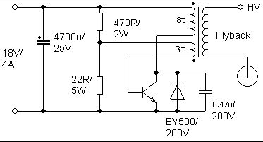
There are very few elements in this circuit, and they are all described on this page. And many parts can be replaced.
The value of the 470 Ohm resistor can be changed. I used a 450 ohm resistor made from three 150 ohm resistors connected in series. Its value is not critical for the operation of the circuit, but to reduce heating, use the maximum resistor value at which the circuit operates.
The lower resistor value can be changed to increase power. I'm using a 20 ohm resistor made from two 10 ohm resistors connected in series. The lower its value, the higher the temperature and the shorter the operating time of the circuit.
The capacitor located next to the transistor (0.47 µF) can be replaced to increase power. The higher its value, the higher the output current (and arc temperature) and the lower the voltage. I settled on a 0.47uF capacitor.
The number of turns on the feedback coil (three-turn coil) can change the power output. The more turns, the greater the current, but not the voltage.
This circuit differs from the more common single-transistor casser in that a diode and a capacitor are added to it, which is connected in parallel with the diode. The diode protects the transistor from voltage surges of reverse polarity, which can burn the transistor. You can use a different type of diode. I used a GI824 diode taken out of the TV. When choosing a diode, pay attention to the voltage and switching speed. To find out if your diode is suitable, find the datasheet for the BY500 diode, and then for your diode and compare the parameters. If your diode is comparable to or better than this one, then it is suitable.
The capacitor is the key to high power output. The transistor generates a frequency set mainly by the primary coil and the feedback coil. The capacitor and primary winding form an LC circuit. The LC circuit operates at a specific frequency, and if you tune the circuit so that this frequency is the same as the transistor frequency, the output power will increase significantly. The theory of an LC circuit is similar to that of a Tesla coil. This circuit can be customized by changing the capacitor value and the number of turns on the primary/secondary windings.
This circuit requires a powerful power supply, which is described below.
power unit
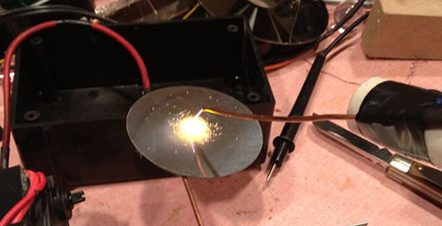
The electric arc is ignited from a distance of 2-3 mm between the terminals of the high-voltage winding, which approximately corresponds to a voltage of 6-9 kV. The arc turns out to be hot, thick and stretches up to 10 cm. The longer the arc, the greater the current consumed from the power source. In my case, the maximum current reached 12-13A at a supply voltage of 36V. To get such results, you need nutrition, in this case this is of primary importance.
 For clarity, I made a “Jacob’s ladder” from two thick copper wires, at the bottom the distance between the conductors is 2 mm, this is necessary for an electrical breakdown to occur, above the conductors diverge, the letter “V” is obtained, an arc is ignited at the bottom, heats up and rises up, where it breaks off. I additionally installed a small candle under the point of maximum approach of the conductors to facilitate the occurrence of breakdown. The video below demonstrates the process of arc movement along the conductors.
![]()
Using the device, you can observe a corona discharge that occurs in a highly inhomogeneous field. To do this, I cut out letters from foil and composed the phrase Radiolaba, placing them between two glass plates, and additionally laid a thin copper wire for electrical contact of all letters. Next, the plates are placed on a sheet of foil, which is connected to one of the terminals of the high-voltage winding, the second terminal is connected to the letters, as a result, a bluish-violet glow appears around the letters and a strong ozone smell appears. The foil cut is sharp, which contributes to the formation of a sharply inhomogeneous field, resulting in a corona discharge.
When one of the winding terminals is brought close to an energy-saving lamp, you can see an uneven glow of the lamp; here the electric field around the terminal causes the movement of electrons in the gas-filled bulb of the lamp. The electrons, in turn, bombard the atoms and transfer them to excited states; upon transition to the normal state, light is emitted.
The only drawback of the device is the saturation of the magnetic circuit of the horizontal transformer and its strong heating. The remaining elements heat up slightly, even the transistors heat up slightly, which is an important advantage; however, it is better to install them on a heat sink. I think even a novice radio amateur, if desired, will be able to assemble this self-oscillator and conduct experiments with high voltage.

"Audio & Video" - information on the latest audio, video equipment and accessories: hardware reviews ( video cameras, TVs, radios, DVD etc.), tests, reviews, advice, everything that will help you navigate and make the right choice of this or that audio or video equipment.
Today, flat-panel LCD (LDC, TFT) or plasma digital TVs appear in almost all homes. And the good old tube ones go into exile in country houses, move to balconies, sheds or simply to a landfill.
And only radio amateurs consider an old TV that has become unnecessary as a source of radio components.
One of the key elements, without which the operation of a kinescope is impossible, is a line transformer.
This is the main part of the line scanning unit, which allows you to generate a very high voltage (about 25-30 thousand volts) at the anode of the kinescope.
This element looks like this (the image is given as an example, there are different types and types of these transformers).
Rice. 1. Line transformer
Shouldn't you throw it away? With the right approach, it can find its place in everyday life. In extreme cases, it is perfect for experiments with high voltages.
What can be done from a liner
The first thing that comes to mind as devices with high voltages are plasma balls (Tesla coils) and “Jacob’s ladders”.
The first ones look like this.

Rice. 2. Plasma ball
Here, a budget incandescent lamp acted as a ball.
And the second one is like that.

Rice. 3. "Jacob's Ladders"
However, in addition to “toys”, you can do more useful things based on the liner:
1.Lighters (for household gas stoves);
2. Air ionizers;
3. Generators for igniting gas-filled lamps;
4. Welding machines (only with full rewinding of transformers).
But since the latest products are not as “spectacular” as the first, let’s look at a couple of examples with beautiful current arcs.
Tesla coil / plasma ball from a regular incandescent lamp
Since the secondary winding will be customized to suit your needs, only a line transformer that has access to the windings, for example, TVS90, TVS-110, etc., will be suitable for experiments. (from old Soviet TVs).
The schematic diagram is shown below.

Rice. 4. Schematic diagram
The secondary winding of the liner is left “as is”, and the primary winding is rewound (or wound over the existing one, if the design of the transformer allows). Make 5 turns of a thick wire with a diameter of about 2 mm (or several, but so that the total cross-sectional area is not less than the specified one). It is best to use insulated wire.
Please note that the lamp may not even be working (with a broken or burnt out filament). So it can actually get a second life.
The LC filter resistor may become quite hot, this is normal. This element should be designed to dissipate approximately 1-2 watts of power.
Another weak element of the circuit is the field-effect transistor. It must be installed on the heat sink using thermal paste (for better temperature conductivity). The heat sink area should be calculated from the 80 W figure received from the transistor.
This is the beauty that comes out in the end.

Rice. 5. Plasma ball
We are not talking about the film of the same name, or the stairway to heaven, but about an interesting phenomenon with electric arcs.
The fact is that during a breakdown, energy (heat) is released, which is transferred to the surrounding air. That, in turn, heating up, according to the law of convection, begins to rise upward, and with it the breakdown discharges between the two conductors rise (after all, the resistance of warm air is less than that of cold air).
So, here's the diagram.

The horizontal transformer itself undergoes the same “refinement”. The primary winding is made with your own hands from thick copper wire. For example, TVS-110L/6 can be used as a “donor”. 5 turns are wound.
The amplifier discussed in the previous diagram for the ball is already integrated into the UC3845 PWM controller.
The breakdown occurs at a distance of approximately 1.5-3 cm. It is at this distance that the electrodes should be installed.
The result may be something like this: a miracle.

Rice. 7. Jacob's Ladder
Safety precautions
The output from the transformer produces a voltage of several thousand volts with a current strength of 90 mA (this is enough to be fatal under certain circumstances).
Do not touch live parts under any circumstances, especially at the output of the line transformer.
If exposed to arcs for a long time, the glass of the lamp may melt, so do not touch it with your hands for a long time.
When turning on the device, it is best to perform all actions with one hand, after putting on dry shoes with rubber soles.
Linear transformers are among the most commonly used by high voltage hobbyists, mainly due to their simplicity and availability. Every CRT TV (big and heavy) that people throw away now has such a transformer.
Unlike many transformers found in other electronics, which are designed to handle regular 50Hz alternating current, and step-down transformers, a line transformer operates at a higher frequency, around 16KHz and sometimes higher. Many modern line transformers produce direct current. Old line transformers produced alternating current, which allowed you to do anything with them. AC line transformers are more powerful because they do not have a built-in rectifier/multiplier. DC line transformers are easier to find and are recommended for this project. Make sure your line transformer has an air gap. This means that the core is not a closed circle, but rather resembles the letter C, with a gap of about a millimeter. Almost all modern horizontal transformers have it, so if you are using a modern horizontal transformer, you don’t have to check this.

This circuit uses the 2N3055 transistor, which is what builders of line transformers love and hate. They are loved for their availability and hated because they usually stink. They tend to burn out quite spectacularly, but the circuit works incredibly well with them. The 2N3055 got a bad reputation when used in simple single-transistor circuits in which high voltage is present across the transistor. This circuit adds several parts that significantly increase its power output. The theory of operation of the circuit is written below.
Scheme
There are very few elements in this circuit, and they are all described on this page. And many parts can be replaced.
The value of the 470 Ohm resistor can be changed. I used a 450 ohm resistor made from three 150 ohm resistors connected in series. Its value is not critical for the operation of the circuit, but to reduce heating, use the maximum resistor value at which the circuit operates.
The lower resistor value can be changed to increase power. I'm using a 20 ohm resistor made from two 10 ohm resistors connected in series. The lower its value, the higher the temperature and the shorter the operating time of the circuit.
The capacitor located next to the transistor (0.47 µF) can be replaced to increase power. The higher its value, the higher the output current (and arc temperature) and the lower the voltage. I settled on a 0.47uF capacitor.
The number of turns on the feedback coil (three-turn coil) can change the power output. The more turns, the greater the current, but not the voltage.
This circuit differs from the more common single-transistor casser in that a diode and a capacitor are added to it, which is connected in parallel with the diode. The diode protects the transistor from voltage surges of reverse polarity, which can burn the transistor. You can use a different type of diode. I used a GI824 diode taken out of the TV. When choosing a diode, pay attention to the voltage and switching speed. To find out if your diode is suitable, find the datasheet for the BY500 diode, and then for your diode and compare the parameters. If your diode is comparable to or better than this one, then it is suitable.
The capacitor is the key to high power output. The transistor generates a frequency set mainly by the primary coil and the feedback coil. The capacitor and primary winding form an LC circuit. The LC circuit operates at a specific frequency, and if you tune the circuit so that this frequency is the same as the transistor frequency, the output power will increase significantly. The theory of an LC circuit is similar to that of a Tesla coil. This circuit can be customized by changing the capacitor value and the number of turns on the primary/secondary windings.
This circuit requires a powerful power supply, which is described below.
power unit
The circuit requires a powerful DC power supply with an output voltage of 12 to 30 volts and 1 to the number of amps you desire. It's a good idea to make a regulated power supply so that the circuit receives exactly the voltage it needs. If the circuit is not assembled correctly and a power supply like this is used, the circuit will burn out. But regulated voltage is not necessary for normal operation.

I used a 300 watt transformer from the amp. It has windings for 2, 4, 15, 30 and 60 volts. The circuit requires 12 to 18 volts for the 2N3055. I often run the circuit at 30V, but not for long, and the transistor is mounted on a powerful radiator. At 15V, the circuit can operate indefinitely, since after 30 minutes of operation, the temperature did not exceed room temperature.
The alternating current from the transformer goes to a 400 W bridge rectifier mounted on the radiator, and from it to a 7800 uF 70V capacitor to smooth out the voltage. Using similar components, you can make your own power supply.

Also, switching power supplies or UPS can be used as a power supply. They are found in laptop chargers, car battery chargers and computer power supplies. They often have a 12V output and a current of up to 10A, which is suitable for this circuit.
This is a very simple circuit to assemble. My assembly is not an instruction or an example, but you can repeat it. Everything is mounted on a piece of MDF, and the elements are laid out loosely to minimize interference from nearby wires and allow for cooling. Use stranded wire. Numerous photographs show in detail the various elements of the circuit, which are often more useful than words.

One of the most important points in the assembly is the transistor heatsink. 2N3055 is manufactured in the TO-3 package. You can buy TO-3 radiators, but they are a little hard to find. I used a heatsink from a computer processor with holes for its contacts on the flat side. Wires from the contacts pass between the blades. The transistor is attached to the radiator with self-tapping screws. Remember to use thermal paste between the transistor and the heatsink. The wires going to the line transformer are attached to it using alligator clips so that line transformers can be changed for experiments.

Another important point is the windings of the line transformer. Enamel insulation of copper wire is good, but it is better to add additional insulation between the core and the windings. The core may have sharp edges, and if the enamel is peeled off, a short circuit may occur. When winding the coils, I removed the metal clamp holding the halves of the transformer together, wound the coils, and then installed it again. On some transformers this is not possible, and the wire will need to be wrapped around the core. The windings must be wound out of phase, which means they wind around the core in opposite directions. This is shown in the photographs.
Usage
When using this circuit, do not perform any manipulations with the connected wires. Also check the temperature of the transistor and resistors during operation, but do this only when the device is unplugged. If any element is noticeably warm, then do not turn on the circuit until it cools down. Capacitors can retain a dangerous charge, so be careful.
Also, wear rubber-soled shoes when working with high voltages and touch the device while it is on with only one hand. Make sure the circuit has been connected to ground after operation to avoid electric shock. Do not attempt to configure an enabled circuit.
There are many things you can do with this circuit, such as using it to power a Tesla coil, melt salt, or just have fun with electric arcs.
List of radioelements
| Designation | Type | Denomination | Quantity | Note | Shop | My notepad |
|---|---|---|---|---|---|---|
| Bipolar transistor | 2N3055 | 1 | KT819GM | To notepad | ||
| Rectifier diode | BY500-200 | 1 | 200 B | To notepad | ||
| Electrolytic capacitor | 4700 uF 25V | 1 | To notepad | |||
| 0.47 µF 200V | 1 | To notepad | ||||
| Resistor |