Arduino mini sizes. Self flashing Arduino Pro Mini.
Instruction
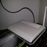
First a couple of words about the programmer itself. You can buy one for $ 2 at any Chinese online store.
The USB-A connector is used, of course, to connect the programmer to the computer.
ISP connector is needed to connect to the programmable board.
Jumper JP1 monitors the voltage on the VCC pin of the ISP connector. It can be 3.3 V or 5 V. If the target programmable device has its own power source, remove the jumper.
Jumper JP2 is used for flashing the programmer itself; This article is not considered.
Jumper JP3 is needed if the target device's clock frequency is below 1.5 MHz.
Two LEDs show: G - power is supplied to the programmer, R - the programmer is connected to the target device.
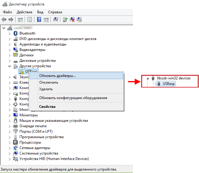
Connect the programmer to the USB port of the computer. Most likely, after some short time, the operating system will report that it was unable to find a driver for this device.
In this case, download the driver for the programmer from the official site http://www.fischl.de/usbasp/. Unpack the archive and install the driver in the standard way. A USBasp programmer should appear in the device manager. Now the programmer is ready to go. Disconnect it from the computer.
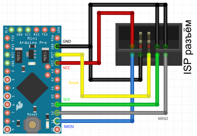
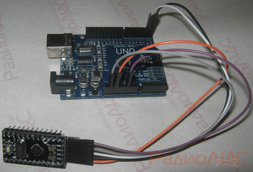
We will use the breadboard and connecting wires - it will be fast and reliable. We connect the connector of the programmer with the findings on the Arduino Pro Mini according to the above diagram.
 |
|||
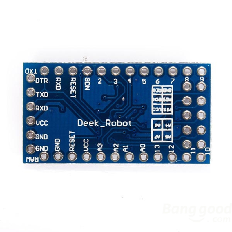
| Arduino Pro Mini - front view | Arduino Pro Mini - rear view |
General information
Arduino Pro Mini is a device based on the ATmega328 microcontroller. It includes: 14 digital inputs / outputs (6 of them can be used as PWM outputs), 8 analog inputs, a quartz resonator, a reset button and contact pads for soldering connectors. The six-pin connector can be used for powering and interacting with the board via USB via an FTDI adapter or a Sparkfun design board.
Arduino Pro Mini is designed for semi-stationary installation in various equipment or installations. The board is specially supplied without soldered connectors, which allows the user to solder the wires or use the necessary types of connectors at their discretion. By pin layout, the Arduino Mini Pro is compatible with the Arduino Mini.
There are two versions of the Pro Mini: one works from 3.3V at a frequency of 8 MHz, the other from 5V at 16 MHz.
Arduino Pro Mini is designed and manufactured by SparkFun Electronics.
Scheme and initial project
Specifications
| Microcontroller | ATmega168 or ATmega328 |
| Operating voltage | 3.3V or 5V (depending on model) |
| Supply voltage | 3.35-12V (for the 3.3V model) or 5 - 12V (for the 5V model) |
| Digital I / O | 14 (6 of them can be used as PWM outputs) |
| Analog inputs | 8 |
| Maximum current per pin | 40 mA |
| Flash memory | 16 KB (of which 2 KB used by the loader) |
| Sram | 1 KB |
| Eeprom | 512 bytes |
| Clock frequency | 8 MHz (for the 3.3V model) or 16 MHz (in the 5V model) |
Nutrition
Arduino Pro Mini can be powered from various sources:
- through the breadboard;
- via an FTDI adapter connected to a six-pin connector;
- from a 3.3V or 5V stabilized power supply (depending on the model) connected to the Vcc pin.
In addition, the board has a built-in voltage regulator, thanks to which it is allowed to supply the board with a supply voltage of up to 12V. If a non-stabilized power supply is used to power the board, make sure that it is connected to the "RAW" terminal and not to the VCC.
Below are the power pins located on the board:
- RAW. To power the board from an unstabilized voltage source.
- VSS. Stabilized voltage 3.3V or 5V.
- GND. The findings of the earth.
Memory
The size of the flash memory of the ATmega328 microcontroller programs is 32 KB (of which 2 KB are used by the bootloader). The microcontroller also has 1 KB of SRAM memory and 512 bytes of EEPROM (from which information can be read or written using the EEPROM library).
Inputs and Outputs
Connection
Arduino Pro Mini provides a number of possibilities for communicating with a computer, another Arduino, or other microcontrollers. The ATmega328 has a UART transceiver that allows serial communication via the 0 (RX) and 1 (TX) digital outputs. The Arduino software package includes a special program that allows you to read and send simple text data to the Arduino via a USB connection.
ATmega328 in the Arduino Pro Mini comes with a stitched loader that allows you to load new programs into the microcontroller without the need for an external programmer. The interaction with it is carried out according to the original protocol STK500 (,).
Automatic (soft) reset
So that each time before loading the program you do not need to press the reset button, the Arduino Pro Mini is designed in a way that allows you to reset it programmatically from a connected computer. One of the pins of the six-pin connector is connected to the RESET pin of the ATmega328 microcontroller via a 100 nF capacitor. When connected to a computer, this output is also connected to one of the lines involved in hardware flow control through a USB-Serial converter: when using an FTDI cable — with an RTS line, when using a Sparkfun prototype board — with a DTR line. When zero appears on this line, the RESET pin, respectively, also goes to a low level for a time sufficient to reset the microcontroller. This feature is used to enable the microcontroller to be flashed with just one touch of a button in the Arduino programming environment. This architecture allows the boot loader timeout to be reduced, since the firmware process is always synchronized with the signal drop on the RESET line.
However, this system may lead to other consequences. When you connect the Pro Mini to computers running Mac OS X or Linux, its microcontroller will be reset each time the software connects to the board. After a reset on the Pro Mini, the bootloader is activated for about half a second. Although the bootloader is programmed to ignore extraneous data (i.e., all data not related to the firmware process of a new program), it can intercept the first few bytes of data from the message sent to the board immediately after the connection is established. Accordingly, if the program running on Arduino provides for receiving any settings or other data from the computer when it is first started, make sure that the software with which Arduino interacts sends out a second after the connection is established.
physical characteristics
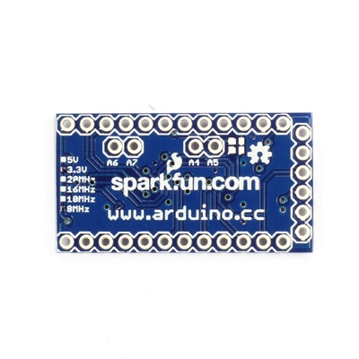
Overall dimensions of the Arduino Pro Mini PCB: 1.8 cm x 3.3 cm.
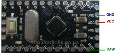
Arduino Pro Mini top view
Arduino Pro Mini bottom view
This board is intended for use in the finished device. Therefore, this microcontroller does not have a built-in chip for communication via USB-UART. There are also no USB connectors for connection and firmware. This allows you to greatly reduce the size of the board, as well as its cost. To connect to a computer and firmware using a special programmer. There are two versions of this board: with 3.3 V power supply and 8 MHz frequency and 5 V power supply with 16 MHz frequency. The younger version of this arduinka uses the ATmega168 chip. This chip has a smaller amount of flash-memory, non-volatile memory, as well as a lower clock frequency. Since the price of different versions of the Arduino Pro Mini is almost the same, we’ll talk about the older version with the ATmega328 chip and a clock frequency of 16 MHz.
Arduino Pro Mini 5 V
This version is equipped with an ATmega328 microcontroller. Unlike his younger brother, he has twice the large amounts of non-volatile and flash memory. And boasts a clock frequency of 16 MHz. You can learn about the firmware of this microcontroller in my article:
Buy Arduino Pro Mini
- The quality is almost the same as the original boards made in Italy.
- The price is several times lower. Italian arduino mini costs about $ 7, and in China this microcontroller will cost $ 1.5
- In Russian stores, the margin is 100-500%. In this case, very often under the guise of the original, the boards can sell Chinese, and even very low quality.
- On aliexpress you can easily find reliable sellers with good reviews.
- You can use discount coupons and cashback services.
Specifications
- Microcontroller: ATmega168 or ATmega328
- Limit supply voltage: 3.3-12 V and 5-12 V
- Digital I / O: 14
- PWM: 6 digital pins can be used as PWM outputs
- Analog outputs: 8
- Maximum current: 40 mAh from one pin and 400 mAh from all pins.
- Flash memory: 16 kb
- SRAM: 1 kb
- EEPROM: 512 bytes
- Clock frequency: 8 MHz and 16 MHz
Power connection to the Arduino Pro Mini
This microcontroller can be powered in three ways:
- An FTDI adapter connected to the 6 corresponding pins.
- By applying a stabilized voltage to the Vcc pin. 3.3 V or 5 V depending on the version
- By applying voltage to the RAW pin. 3.3-12 V or 5-12 V, depending on the version
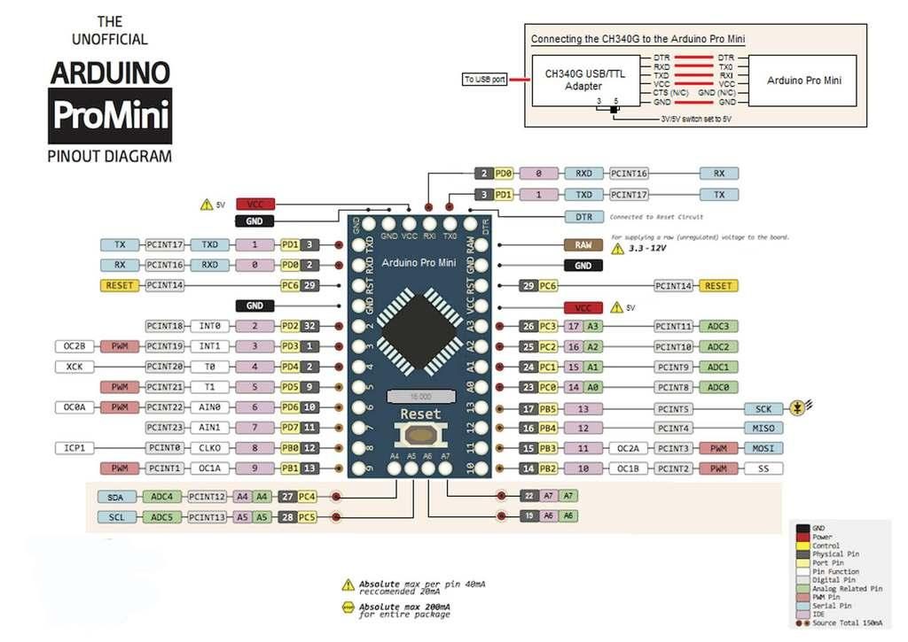
As it was already written above, the board has 14 digital pins. On the board they are labeled with a sequence number. They can be both an entrance and an exit. The operating voltage of these pins is 3.3 V or 5 V.
The analog pins on the board are marked with the leading "A". These pins are inputs and do not have pull-up resistors. They measure the voltage applied to them and return a value from 0 to 1024 when using the analogRead () function. These pins measure voltage to the nearest 0.005 V.
Pulse Width Modulation (PWM) Arduino Pro Mini
The PWM outputs of this board are not labeled in any way. You just need to remember the numbers of digital outputs that are connected to a pulse-width generator. The Arduino Pro Mini has 6 PWM pins, these are pins 3, 5, 6, 9, 10 and 11. To use PWM, Arduino has a special function.
Other pins:
- 0 (Rx) and 1 (Tx) are used to transmit data over the serial interface.
- Conclusions 10 (SS), 11 (MOSI), 12 (MISO), 13 (SCK) are calculated for communication via the SPI interface.
- Also on the output D13 has a built-in LED.
- A4 (SDA) and A5 (SCL) can be used to communicate with other devices via the I2C bus. You can read more about this interface on Wikipedia. In the Arduino IDE development environment, there is a built-in “wire.h” library for easier work with I2C.
physical characteristics
Arduino Pro Mini has the following dimensions: length 33 mm and width 18 mm, and weighs only about 10 grams. The distance between the leads is 2.54 mm.
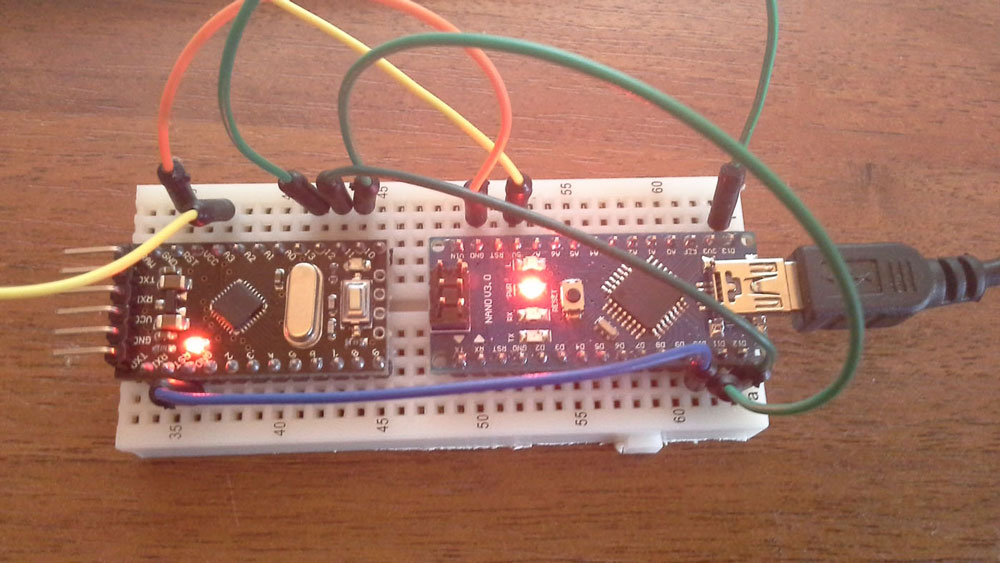
After purchasing the Arduino Mini Pro board, some users are faced with the problem of firmware, since in order to flash this board, you must also purchase a special programmer. In this regard, you will be interested in how to flash the board without a programmer? Fortunately, this is quite simple. In this article we will take a closer look at how to flash or flash the Arduino Pro Mini. Let's figure it out. Go!
For flashing you need Arduino Uno. The first step is to connect GND to ground, UCC with a plus, RXI and NX0 with the same inputs to Uno, and GRN with a reset. It is best to apply a three-voltage. When power is applied to the board, the red indicator will light. Don't forget to remove the ATMEGA controller from Uno.
Now you need to connect the board to the computer. Then run Sketch on your PC. While in the main utility window, open the “File” menu and click on the “Examples” item, then hover over the “Basics” section and click “Blink” in the list that appears. After that, go to the top panel and open the “Tools” menu. Select the item "Fee" in it. In the list of boards you will need to mark the line “Arduino Pro Mini (5V, 16MHz) w / ATmega328” instead of the one that is marked by default. Also, do not forget to specify the required com-port in the settings.
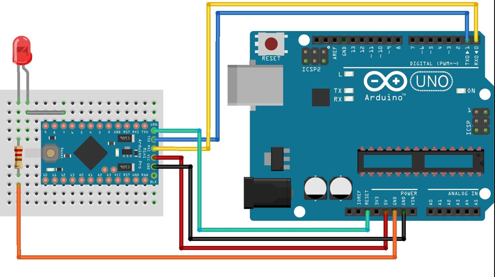
Then click the Download button in the program. As soon as the word “download” appears on the bottom line, click on the “reset” board. On the screen you will see a message that the download is complete. Is done. Re-flashing successful.
Now consider how to do the same, only through Nano. Open Sketch and go to the "File" menu, select the "Samples" section. In the list that appears, click on "ArduinoISP". Then you need to go to "Tools", select "Fee" and check "Arduino Nano".
Perform Nano firmware using the ArduinoISP sketch. Check the port speed in the setup function. This is what the speed will be during the Pro Mini firmware. In standard Sketch, the speed is 19200.
Having prepared the Nano, proceed to the assembly of the breadboard to reflash the Pro Mini. Connect + 5V to Vcc, connect GND to the same input, D10 to RST, and D11, D12 and D13 to the same inputs on the Pro Mini.
Now you need to connect the Nano to the PC. Before you start flashing, make sure that you use equal port speeds, focusing on the speed of the Sketch. Find the text files “boards” in the folder “arduino”. Open it, find the line:
pro5v328.name = Arduino Pro Mini (5V, 16 MHz) w / ATmega328
If you are using a different version, select the appropriate one. Check the set speed. You should also check the settings in the text file “programmers”.
If the settings are OK, start / restart the IDE. After that, go to the "Tools" menu and specify the board that you want to flash along with the type of programmer "Arduino as ISP".
In the next step, open the “File” section and click on the “Load via programmer” item. As in the case above, it is necessary to press the reset button on the board in order to successfully perform the flashing. Everything. Is done.
Now you will know how to flash or reflash Arduino Pro Mini without a special programmer. Write in the comments if this article was useful for you, tell other users about your experience with the Arduino firmware, and ask any questions you may have about the topic discussed.
Arduino Pro mini - a compact version of the Arduino platform, designed to build all sorts of projects that are not large in size. The platform is 100% compatible with other Arduino platforms, such as the Arduino UNO for example, but much more compact. In this article, I will review the Chinese analogue of the Arduino Pro mini, tell you how it differs from the original, how this board differs from other Arduino platform motherboards, and also how to connect it to a computer to upload a sketch to it. In conclusion, let us make sure that the board is working, using the “blink” sketch as an example.
I bought this analogue of the Arduino Pro mini on Aliexpress for $ 1.30, while the original board on the manufacturer's website costs € 13. The difference in price is the first major difference between the Chinese counterpart and the original.
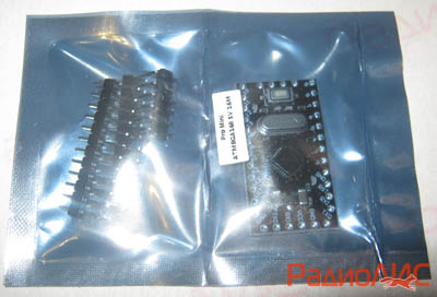
The fee came in an antistatic bag. Included were also contact pads.
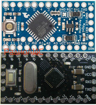
For comparison, the top board is the original Arduino Pro mini, below is my Chinese equivalent. In terms of the number and location of the contacts, the board is identical to the original, except for contacts A4, A5, A6 and A7. On the original board, these contacts are located in the center, on the analog they are on the left.
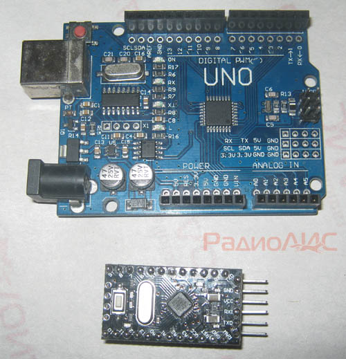
In order to have a visual idea of the size of the board, I will bring it next to my Chinese counterpart Arduino UNO. Pro mini was able to be reduced in size by removing the USB connector, matching the board with the USB port, and the power connector was also removed. The Chinese equivalent is 100% compatible with all modules, drivers, sensors that work with the original version.
The original modern Arduino Pro mini board is based on a microcontroller. ATmega328, on the same as Arduino UNO. Earlier models of this board were built on a microcontroller. ATmega168.
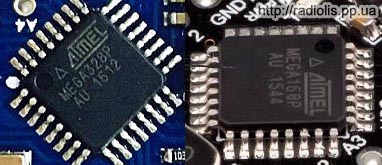
The Chinese analogues of the Arduino Pro mini are currently being built as ATmega328so on ATmega168. This is the second difference from the original analogue. The ATmega168 board will cost less than the ATmega328. The main difference between these controllers is that the ATmega328 contains two times more memory onboard than the ATmega168.
|
Microcontroller Differences |
ATmega168 |
ATmega328 |
|
16 KB |
||
But this does not mean that on ATmega168 it will not be possible to build a project that was developed on the board with ATmega328, because 16 KB will be quite enough for many sketches. Still, if you need double the amount of memory, read the description of the board before you buy. When buying my Chinese counterpart, I chose a board for $ 1.30 with an ATmega168, instead of a board with an ATmega328 for $ 1.93. As you can see, here too we can save on the purchase.
The original Pro mini board comes in two power options: 5 and 3.3 volts. In the version running at 3.3 volts, the microcontroller operates at a frequency of 8 MHz, in the 5-volt version it operates at a frequency of 16 MHz. Chinese counterparts are also produced in 2 versions. My board works from 5 volts.
Visually, the frequency of the controller can be determined by the quartz installed on the board, if it is in a large case, it can clearly see the frequency at which it works: 8 or 16 MHz.
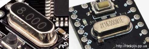
Fragments of boards with quartz operating at different frequencies.
Pro Power Arduino Pro mini.
GND, VCC and RAW pins are used to power the board.
GND- This is a minus power (land).
VCC- used to supply power 3.3 or 5 volts, depending on the version of the board. This connector is supplied strictly with the voltage for which the board is designed. The voltage from this contact goes directly to the microcontroller, if it is higher than necessary, the latter can fail.
If you are going to power the board with a high voltage, then the “+” power should be connected to the connector RAW. Up to 12 volts can be supplied to this connector, no matter what voltage the board is designed for. The voltage from this contact is fed to the voltage regulator, which converts it to the required value, and only then is fed to the controller.
If it so happens that you bought the board and do not know what voltage it is rated for, apply 5 volt to the RAW connector and measure the voltage at the VCC connector. If the board is designed for 3.3 volts, then the corresponding voltage will be at VCC, if it is at a VCC of 5 volts, then the board is 5 volts.
The digital and analog outputs of the Pro mini correspond to the number of outputs like the UNO board: 14 digital and 6 analog. The contacts A4 (SDA) and A5 (SCL) are used to connect various devices via the I2C bus.
About firmware Arduino Pro mini.
Having become one of the smallest Arduino platform motherboards, the Pro mini motherboard has gained a disadvantage - you cannot flash the motherboard without third-party help. I'll tell you about all the possible ways to fill sketches in Pro mini.
Arduino Pro mini firmware with Arduino UNO board.
This is not the easiest way, because not everyone has a UNO card and buying it specifically for firmware Pro mini boards is not advisable. But since I have a Chinese equivalent of UNO, I will start with this method. To implement this method, a driver must be installed on the UNO board and the number of the COM port to which this board is connected is determined. How to do this is described in the article about the Chinese equivalent of Arduino UNO.
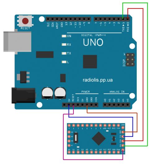
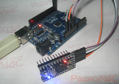
We connect the board as in the picture. findings GND, Txand Rxconnect with similar. Conclusion " VCC"On the Pro mini board connect with the output" 5V" or " 3V3"On the UNO board. If you have a 5 volt version of Pro mini, then connect with the output "5V", as in my version. If the version is 3 volt, connect to the “3V3” on the UNO board. Conclusion RESETon the UNO board we connect to the output DTRon the Pro mini board. On the original board output DTRdesignated as GRNIn general, this is the same thing.
When everything is connected, runArduino IDE.

Select the board in which you want to sew a sketch:« Instruments» - « Pay:"And choose your fee, in this case it is"Arduino Pro or Pro Mini».
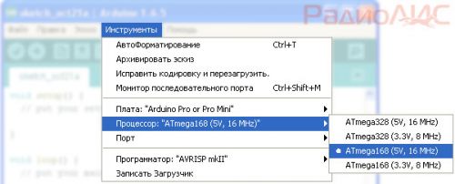
Since the Pro Mini boards can use different microcontrollers (ATmega168 or ATmega328), as well as different supply voltages (3.3v or 5v ), choose your configuration: " Instruments» - « CPU:"In this example, select" ATmega168 (5 V, 16 M H z)».
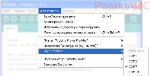
Choose the port to which the board is connectedUNO: « Instruments» - « Port:» in my case it is "COM7».
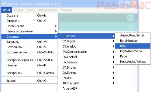
Let's try to fill in the first sketch and make sure that the board works. Select the sketch "Blink ", The meaning of which is to flash the LED built into the board:" File» - « Samples» - « 01. Basics» - « Blink».
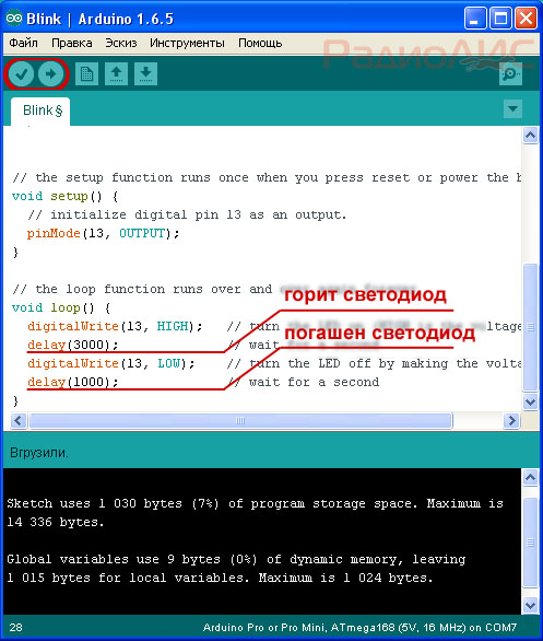
Using the “ Check"And" To load»A sketch is checked for errors and loaded into the board. If there are no errors, the blue LED will start blinking on the Pro Mini board.
You can play with the values in the sketch and change the LED burning time and the time of the extinguished LED, re-fill the sketch and see that the LED will flash differently.
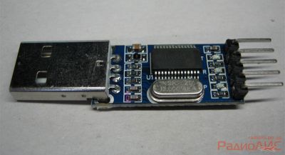
Arduino Pro mini firmware using a USB to TTL adapter.
I have already told about one of these adapters on a PL2303 chip, now it's time to try it out in practice. There are two versions of this adapter, one without contact GRN (DTR), like mine, the second with this contact. Those with contact are at least twice as expensive as those without contact.
If you use an adapter without a GRN (DTR) contact, connect it to the Pro mini as in the picture.
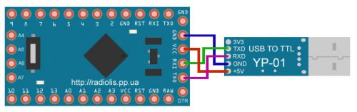
If you have a 3 volt version of Pro mini, then contact VCC of the board, you need to connect to contact 3V3 USB adapter.
When everything is connected, launch the Arduino IDE. Select the board version, processor and port, select the “Blink” sketch, just like in the UNO example above.
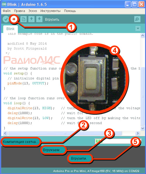
To fill the sketch you need:
1.
Click on the " To load».
2.
The process of compiling the sketch will begin, which can be understood from the inscription " Compiling a sketch ...».
3.
As soon as this inscription changes to “ Loading ...».
4.
Briefly push the button on the Pro mini board RESET.
5.
The sketch will be poured into the board, on the successful completion we will be able to watch the inscription " Fired up"And on the flashing LED on the board.
If you have a USB to TTL adapter in your hands, connect it to the DTR pin (also known as GRN, RESET) with the corresponding RESET pin on the Pro mini board. In this case, when you fill in the sketch, you will not have to press the RESET button, the board will reset itself.
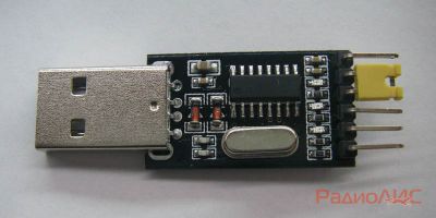
This adapter as well as on PL2303 allows flashing the Arduino board. Connection diagram is as follows:
There are also other USB adapters for the Arduino Pro mini firmware, for example, on an FT232 microcircuit, but since this adapter is more expensive, I do not take it into account.
Arduino Pro mini firmware via COM - port.
Directly flashing the board through the COM port will not work, since the COM port and the Pro mini have different logic levels. To coordinate them, you need to use an adapter on the MAX232 chip. The microcircuit itself is not expensive, but I don’t know if it is worth bothering to install Pro mini with this adapter if it is not cheaper at the price than buying a USB adapter on PL2303.
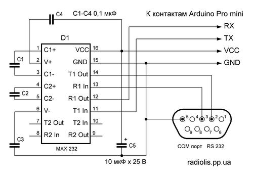
In any case, present the scheme.
In order to make sure of the efficiency of this method, I had to assemble this scheme myself on the breadboard. The fee is in progress ...