What is an ethernet network connection. So what is Ethernet and how does it work
Introduction The Russian market of on-line data transmission services is at the initial stage of its development. The main limiting factor is the discrepancy between the high prime cost of services and the solvency of consumers, as a result of which only medium and large corporate users could afford such services so far. It is no secret that to reduce the cost of services, the most important role is played by the choice of data transmission medium for the organization of the “last mile”, that is, the lines along which subscribers' premises are connected to the operator's access points. When building a network designed for the mass user, the choice of technology for the “last mile” becomes crucial from the point of view of the impact on tariffs. Currently, the following means for organizing the “last mile” are known and widely used in urban environments: - telephone copper wires; fiber optic cables; - television cable networks; - radio broadcasts (radio-Ethernet technology); - satellite television channels. For many years, the possibilities of high-speed data transmission did not extend to millions. lei small business and private subscribers who, for understandable economic reasons, cannot afford to contain a dedicated fiber-optic line. And although the demand of these groups of subscribers for digital transmission technologies was constantly growing and growing, until recently they only had to rely on the data transmission tools that use the lines of the public telephone network. DSL (Digital Subscriber Line) technologies are one of the main means of solving problems of this kind. Copper subscriber telephone line is in the stage of evolutionary transition from analog network intended only to provide telephone connection, to a broadband digital network capable of providing voice, high-speed data, as well as other equally important communication services. Maintaining such a network requires not only the availability of appropriate modern equipment, but also a completely new approach to managing the operation of the cable subscriber telephone network. The network consisting of pairs of twisted wires, which was originally intended only to provide telephone communications between various subscribers, is gradually turning into a broadband network. channels capable of supporting high-speed data transmission and other broadband telecommunications services. Designed for analog telephone lines, the technology (analog modems designed for transmission over telephone lines) has a very limited speed data transfer - up to 56 Kbps. But, due to the use of modern technologies on the subscriber cable network, designed specifically for twisted pairs of wires, the same lines that were previously used for traditional telephony and data transmission can support cost-effective high-speed data transmission, while maintaining the possibility of simultaneous use of subscriber lines and for traditional telephone service. The new stage of development was overcome through the use of DSL technology. For end users, DSL technology provides high-speed and reliable connection between networks or the Internet, and telephone companies are able to exclude data streams from their switching equipment, leaving it exclusively for traditional telephone communication. Providing high-speed data transmission over a copper two-wire subscriber telephone line is achieved by installing DSL equipment at the subscriber terminal line and the "end stop" backbone speed data transfer, which should be located at the telephone exchange, which is connected to this subscriber line. If high-speed data transmission is organized on a subscriber line using DSL technology, information is transmitted in the form of digital signals in a band of much higher frequencies than the one that is commonly used for traditional analogue telephony. This allows you to significantly expand the communication capabilities of existing twisted pairs of telephone wires. The use of DSL technology on the subscriber's telephone line made it possible to turn the subscriber cable network into a part of the high-speed data transmission network. Telephone companies were able to increase their profits using the existing cable telephone network to provide their subscribers with high-speed data transfer at an affordable price. In addition to providing high-speed data transfer, DSL technology is an effective means of organizing multi-channel telephone services. With the help of VoDSL technology (voice over DSL) you can combine a large number of telephone (voice) communication channels and transfer them over one subscriber line on which DSL equipment is installed. Providing Internet access is one of the main functions of modern digital networks. The width of the band used depends on the technology used for high-speed data transmission. The urgent need for high-speed data transmission has led to the creation of technologies and appropriate DSL equipment. To ensure a proper level of service, for example, in cities, access equipment must be installed on hundreds of telephone exchanges. Only after the installation of the necessary equipment can this service be offered to potential users. Providing subscribers with a high-speed data transfer service includes installing the necessary equipment at the subscriber, proper connection and preparation of the line connecting the user equipment with the equipment installed at the telephone exchange and the start of maintenance. At the same time, there is a need for training staff with the ability to work with DSL equipment and technologies for all organizations involved in the provision of this service. Not all lines support DSL technology. Telephone company technicians should be able to qualify the lines not only from the point of view of their use for high-speed data transmission using DSL technology, but also to determine the specific DSL technology that can be used on a given subscriber line. Ideally, if at least the verification of potential users' lines is carried out in advance, which will allow, after receiving any service request from any of these users, provide the required service almost without delay. Providers should have physical access to subscriber lines and test equipment that allows remote analysis of digital high-frequency signals and the state of the physical line, which will allow you to monitor the work of the subscriber line, to search for and eliminate malfunctions. using a standard analog telephone service subscriber dials a number that allows switching equipment telephone network to establish a connection with another person or a modem. In the event of a malfunction, for example, a provider modem, a disconnection occurs and to establish a connection, the subscriber must dial the telephone number again. The DSL connection is a permanently on connection that connects the user equipment to the access multiplexer. In case of damage at the station of the equipment providing the connection with this user, the latter will not receive service until the provider eliminates the malfunction in his equipment. Therefore, in case of damage to the access equipment, the provider must be able to quickly switch the user to the backup equipment and fix the malfunction. as networks become increasingly complex in terms of the services provided and the functions performed, management systems must also develop bye Advanced tools and management tools reduce the overall cost of monitoring network status and control. Nowadays, technologies that provide high-speed Internet access and network connection between themselves are more available than ever. DSL technologies can expand the use of such services to those segments of the market that have not previously been covered. However, the large-scale introduction of new technologies leads to a gradual transition from the analog subscriber network to the digital subscriber network. The transition to a new stage of development leads not only to the creation of new generation equipment, but also requires the use of appropriate instruments, training of service personnel for new methods of work and a completely different approach to managing the network of subscriber telephone lines.
1. Technology of asynchronous digital subscriber line 1.1. General description of the ADSL technology. The possibilities of a copper twisted pair for the transmission of a high-frequency analog signal are well known. Analog modems allow you to reach speeds up to 56 Kbps with a standard telephone channel. Using similar modulation techniques, ADSL technology allows achieving a downstream rate (from station to user) up to several Mbps. On a low-speed channel from user to station, this technology allows the user to control the downward flow. It should be noted that modern modulation and coding algorithms provide an ADSL speed that approaches the theoretical limit. The high downstream speed is chosen because most home user applications are asymmetric. Business users who need symmetrical high-speed applications use optical or coaxial cable to provide high-speed two-way communication. Therefore, the ADSL technology was developed primarily for the home users market. In this connection, the user can continue to use the existing telephone connection. In practice, this means that the user can make telephone calls during data transfer using ADSL equipment. A brief history of the evolution of modems using unshielded twisted pair. In 1881, Graham Bell invented analog modemi.e. phone. After that, it took 80 years to invent digital modems. Modems using the standard telephone channel are shown in Table 1. Table 1 Modems using the PM channel
Modems that use a dedicated pair of balanced cable are listed in Table 1.1. Table 1.1 Modems using dedicated pairs of balanced cable
ADSL concept. It was offered at the beginning of this decade by AT & T Bell Laboratories and Stanford University. Since then, the path has been traversed from computer emulations and laboratory prototypes to the release of standard systems that will soon grow into integrated systems. The principle is to transmit a high-speed downstream to a user and a low-speed upstream from the user to the network without affecting telephony ( See Figure 1). Figure 1 - The spectrum of frequencies used. In high-speed downstream and low-speed upstream digital information is transmitted. In addition to this, ADSL technology has the important ability to multiplex digital information at higher frequencies, compared to a traditional channel. In other words, users using analog telephony can continue to use it simultaneously with ADSL. This function is carried out using a special device - a splitter. The bandwidth of the upstream and downstream is several Kbps and several Mbps, respectively. Naturally, with increasing distance, the maximum achievable bandwidth is falling. For example, an ADSL device operating at a speed of 2 Mbit / s allows you to connect multiple users at a sufficiently long distance. While ADSL devices operating at speeds of 6 Mbit / s and more, will allow users to connect at a much shorter distance. Since the ascending stream is transmitted at a lower frequency than the descending one, crosstalk will be much lower than with symmetric systems. The absence of such interference allows the use of ADSL devices over long distances. The ADSL transceiver operates at higher frequencies than standard telephone devices, therefore, when there is filtering that provides protection against unwanted noise (arising from the transmission of the number by the decade current and when the ringing current is sent), the ADSL devices can use one telephone pair with telephone devices. Thus, the ADSL technology assumes the presence of a pair of high-speed modems to provide access to rock band services. One modem is installed in the ADSL multiplexer and is connected via a high-speed network to a service provider that provides Internet access, video on demand, and so on. Another modem is installed at the user's premises and connected to one or more Service Module (SM). The SM is an end-user device, such as a personal computer (PC) (See Figure 2). 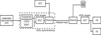 Figure 2 - The principle of the organization of ADSL 1.2 Areas of use ADSL Speed requirements. Obviously, most subscriber services are asymmetrical. In other words, the user receives a large amount of information, while the speed of information transfer is much less. Particularly high downstream speeds require video service. Thus, the ADSL device should provide flexibility in choosing the speed, the user should be able to independently determine the number of channels and their speed when receiving data. In recent years, the use of the Internet has increased significantly, and the amount of information that the user receives from the network has also increased. In this regard, modern ADSL modems provide the user with two interfaces. The first interface is Ethernet, with the help of it any personal computer can be connected to the modem. The other is the ATM interface, which allows, through the use of a special terminal, to receive a video signal on a TV set, and is also designed for the further growth of ATM technology. Services and areas of application of ADSL: Remote access. The end user has the ability to access a workstation, printers, faxes or remote LANs: - downstream. Video quality CATV (4 Mbps) + voice + data; - upstream. Voice + data (64 Kbps). Video conference. The end user has the ability to receive video from a remote video conference, in this case the video will be transmitted downstream, and the audio information in an upstream: - downstream. Low-quality video (1.5 Mbit / s) + voice + graphics; - upstream. Voice + graphics + date (all - 384 Kbps). Video on demand, interactive television. The end user can access real-time video and / or pre-saved video or graphics, and can also search using the menu: - downstream. Quality VHS (1.5 Mbit / s), CATV (4 Mbit / s), high (6 Mbit / s); - upstream. Remote control using VCR (16 kbps). Music is available on request. The end user can access the music through the service provider's network: - downstream. High quality audio (384 kbps); - upstream. Remote control (stop, pause, ...) (100 bps). Interactive games. The end user has the opportunity to participate in an interactive game through remote server with another user: - downstream. High-quality video (6 Mbit / s) + audio; - upstream. Joystick or mouse (64 Kbit / s). The speed of receiving and transmitting data required to implement any of the considered applications is provided by ADSL technology. 1.3 Application problems ADSL Options telecommunication system. The maximum speed is required and, at the same time, the minimum probability of an error. This can be achieved by increasing the transmit power and / or increasing the bandwidth and / or complicating the system. Of course, the minimum possible power, bandwidth and system complexity is required. In addition, the telecommunications system has limitations on these parameters. Here the restrictions imposed on the power and bandwidth are stipulated. On the other hand, we need to ensure maximum use of the system. The maximum number of users should be able to reliably access services with minimal latency and maximum protection against interference. Here's what the user needs. There are certain theoretical constraints affecting the final product: - theoretical Nyquist minimum bandwidth; - Shannon-Hartley power theorem and Shannon's associated limit; - restrictions imposed by the government, for example, on the allocated frequency range; - technological constraints, such as complex components. Nyquist criterion. Nyquist studied the problem of determining the shape of the received pulse, which would allow to avoid intersymbol interference (Inter-Symbol Interference - ISI) in the detector. He was shown that for detection without ISI Rs symbols per second, the minimum necessary bandwidth is Ѕ Rs Hz. This rule is carried out under the condition that the frequency response of the transmission coefficient is rectangular: Wmin = 1 / 2Rs. (1) When using a transmission medium having a form of frequency response that differs from a rectangular one, the equation will take the following form: Wmin = Ѕ (1 + r) Rs, (2) where r is a number from 0 (rectangular shape) to 1. Conclusion. The Nyquist criterion imposes limits on the transmission rate in characters per second for a given bandwidth. For example, telephony uses a bandwidth of 3 kHz. In this case, the maximum achievable speed will be 6000 characters per second. Shannon-Hartley theorem. In this theorem, it is determined that the maximum speed (bit / s) can be achieved by increasing the bandwidth and signal power and, at the same time, reducing noise. From formula (1), it can be seen that double the signal-to-noise ratio (SNR). This can be achieved by doubling the power of the useful signal, or by reducing the noise. Conclusion. The Shannon-Hartley theorem limits the information rate (bit / s) for a given bandwidth and signal-to-noise ratio. To increase the speed, it is necessary to increase the level of the useful signal, in relation to the noise level. Problems with modems. We have a channel with a known bandwidth and signal-to-noise ratio. On the one hand, the Nyquist criterion limits the maximum number of characters that can be transmitted without error. On the other hand, the Shannon-Hartley theorem limits the maximum number of bits that can be transmitted without error. Based on these two constraints, we can calculate the number of bits per character that must be achieved in order to achieve maximum (not necessarily optimal) speed. However, it remains unclear how to implement the required number of bits in a symbol, i.e. Various modulation technologies are possible. Various phenomena that affect the performance of a twisted pair transmission can be divided into the following categories: attenuation, pulse dispersion, reflections, inconsistent transceiver, cable diameter changes, noise and interference, white noise, crosstalk, radio interference frequency, impulse noise. Fading. The impulse transmitted over twisted pair is received on the other side with a smaller amplitude. The attenuation in the cable limits the distance at which twisted pair cable can be used without regenerators. The frequency characteristics of a twisted pair are significantly affected by the surface effect, as a result of which high frequency currents flow in the surface layer of the conductor. The result is a stronger attenuation at high frequencies. The problem can be solved by increasing the power of the transmitted signal: - the maximum signal power is limited due to the appearance of crosstalk, thus the received signal always has a small amplitude; - it should be noted that to ensure electromagnetic compatibility It is necessary that ADSL systems do not interfere with the operation of radio transmitting systems. This condition also imposes restrictions on the power of the transmitted signal - the ADSL device must operate on both a short line with 0 dB attenuation and a long line with 55 dB attenuation, since it is not known on which line this device will be installed. Pulse dispersion. This problem is as follows: the shape of the impulse arriving at the remote end differs from the original form. With increasing cable length, the impulse is expanding more and more, this effect is called dispersion. This effect (due to the frequency dependence of the channel transfer function) leads to what is called intersymbol interference (ISI). In linear channels that have frequency limitations and are dependent on the frequency of attenuation and delay, there is a dispersion of pulses, which leads to errors in the detection process. This effect has the most effect on short pulses, which leads to restrictions for high-speed systems. ISI can be partially compensated with adaptive channel compensators. It is necessary, however, to note that compensation is an amplification and, thus, has limits related to the quality of the received signal (noise). Reflections. Reflections in the cable may occur due to mismatch of the transceiver and changes in cable diameter. White noise. It has many causes of appearance and it is almost impossible to completely suppress it. This means that even if you isolate all sources of noise and interference, white noise will still limit system performance. Transient noise. They introduce the most serious limitations to the subscriber section of the network. The essence of this phenomenon lies in the capacitive coupling between the pairs of cable. Cross talk can be at the near end (Near End CROSSTalk - NEXT) and at the far end (FarEndCROSSTalk – FEXT): - NEXT is defined as crosstalk between the receiving and transmitting pair at one end of the cable; - FEXT is defined as crosstalk in the receiver due to effects of a transmitter operating on a different pair of cable at the remote end of the receiver. It should be noted that the interference effect at FEXT, unlike NEXT, passing through the communication line, attenuates as well as the transmitted signal. Thus, in the case that signals are transmitted in both directions, the NEXT cable will be significantly larger than the FEXT. If the signals use a common frequency band, for example, in the case of echo cancellation, NEXT will make the largest contribution to crosstalk. Also NEXT will be higher when using closely located modems. This means that NEXT is more important at the location of the ADSL - multiplexer. Own crosstalk. In addition to the crosstalk described earlier, there are also so-called self-crosstalk. In fact, this type of interference is not transient, since it is not an interference between the receiver and the transmitter. This type of interference is caused by an incomplete separation of the directions of reception and transmission in the differential system, and is also a consequence of the non-perfect matching of the receiver and transmitter. Attenuation on the line can reach 55 dB, therefore, in order to receive a signal with a level higher than that of its own crosstalk, the differential system must ensure attenuation no worse than 55 dB. As in the case of NEXT, this problem exists only when transmitting and receiving signals in the same frequency range, for example, when using echo cancellation. Radiofrequency interference. The access network is exposed to a wide range of radio frequency interference (RadioFrequencyInterference - RFI), for example, from long-wave or mid-wave broadcast transmitters. Despite the fact that copper twisted pairAs a rule, it is well balanced and therefore little affected by this phenomenon (usually RFI is more susceptible to rural networks with overhead cables), means must be provided to protect transmission systems from RFI. It should be noted that based on the requirements for electromagnetic compatibility (Electro-Magnetic Compatibility-EMC) transmission systems (ADSL) should not be exposed to interference with radio transmission equipment. This fact also imposes restrictions on the power transmitted through the signal line. An important advantage of one of the modulation methods used in ADSL-DMT is that it satisfies both the requirements for resistance to radio frequency interference and the magnetic fields generated. Impulse noise. This phenomenon is characterized by rare noise emissions of large amplitude, the cause of which may be switching stations, pulse dialing, ringing, proximity to railway stations, factories, etc. The characteristics of the impulse noise depend on the type of station used, and thus are specific for each country. 1.4 Solutions to ADSL problems Separation of transmitted and received data. When using ADSL data is transmitted over a common twisted pair in duplex form. In order to separate the transmitted and the received data stream, there are two methods: frequency division of channels (Frequency DivisionMultiplexing - FDM) and echo compensation (EchoCancelation - EC). Frequency division of channels. When using this mechanism, the low-speed data transmission channel is located immediately after the frequency band used to transmit analog telephony. The high-speed received data channel is located at higher frequencies. The frequency band depends on the number of bits transmitted by one signal. Echo compensation. This mechanism allows low-speed channel of transmitted data and high-speed channel of received data to be located in the common frequency range, which allows more efficient use of low frequencies, on which cable attenuation is less. Comparison: - echo compensation improves performance by 2 dB, however, is more complex in implementation; - EC benefits are growing when using higher-speed technologies such as ISDN or video telephony at 384 kbit / s. In these cases, the FDM requires the allocation of higher frequencies for the high-speed channel of the received data, which leads to an increase in attenuation and a reduction in the maximum transmission distance; - The ADSL standard provides for interaction between various equipment using both the FDM mechanism and the EC, the choice of a specific mechanism is determined when a connection is established. In the event of interference with other services, a transceiver using the EU performs better. At a speed of 1.5 Mbit / s, the difference in the maximum distance is 16% in favor of the EU, but at a speed of 6 Mbit / s, the difference drops to 9%. If you take into account your own crosstalk (i.e. ADSL systems, a transceiver using FDM performs better at speeds above 4.5 Mbps. This is due to the fact that a transceiver with FDM is limited only by the presence of the FEXT effect, whereas a transceiver using the EC mechanism is influenced by both the FEXT and its own NEXT. Usually modems are located close to each other at the input of an ADSL multiplexer; in this case, the NEXT parameter has the greatest value, which is why the FDM mechanism is preferred. Transmission methods. One of the most important issues in the standardization of transmission systems is the choice of the type of modulation used. In the ADSL standardization process, ANSI identified three potential modulation types: - quadrature amplitude modulation (Quadrature Amplitude Modulation - QAM); - amplitude-phase modulation with carrier suppression (Cariereless Amplitude / PhaseModulation - CAP); - discrete multi-tonal modulation (DiscreteMeteTetemo) . Studies have shown that DMT is the most productive. In March 1993, the ANSI T1E1.4 working group defined a basic interface based on the DMT method. Later, ETSI also agreed to standardize DMT for use in ADSL. Quadrature amplitude modulation. For transmission in a single frequency band, the usual method is amplitude modulation (Pulse Amplitude Modulation - PAM), which is to vary the amplitude in discrete steps. QAM uses modulation of two parameters - amplitude and phase. In this case, relative phase modulation is used to encode the top three bits, and the last bit is encoded by choosing one of two amplitude values for each phase signal. Theoretically, the number of bits per character can be increased by increasing the QAM bit depth. However, as the bit depth increases, it becomes more and more difficult to detect phase and level. Amplitude-phase modulation with carrier suppression. ATS as well as QAM uses modulation of two parameters. The shape of the spectrum in this modulation method is also similar to QAM. Discrete multi-tone modulation (DMT). DMT uses multi-carrier modulation. The time is divided into standard “symbol periods” (symbol period), each of which carries one DMT, a symbol that carries a fixed number of bits. Bits are grouped together and assigned to signal carriers of different frequencies. Therefore, from the frequency point of view, the DMT splits the channel into a large number of subchannels. The bandwidth depends on the bandwidth, i.e., the higher-bandwidth subchannels carry more bits. Bits for each subchannel are converted to a complex number, the value of which determines the amplitude and phase of the corresponding signal carrier frequency. Thus, DMT can be represented as a set of QAM systems that operate in parallel, each at a carrier frequency corresponding to the frequency of the DMT subchannel (see Figure 3). So, the DMT transmitter essentially modulates by forming packets of signal carriers for a corresponding number of frequency subchannels, combining them together and then sending them into a line as a “DMT symbol.” Modulation / demodulation using many carriers is implemented in a fully digital scheme using the evolution of Fast Fourier Transform FFT (FastFourierTransform – FFT). Early implementations of DMT did not function well due to the difficulty of ensuring equal spacing between subchannels. Modern implementations function successfully due to the presence of integrated circuits implementing FFT hardware conversion, which allows you to effectively synthesize the sum of QAM-modulated carriers.
 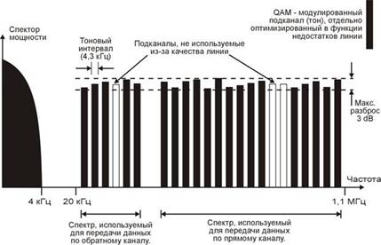 Figure 3 - Frequency distribution for ADSL signaling. To achieve optimal efficiency, the main task is to choose the number of subchannels (N). For subscriber telephone lines, the optimal value is N = 256, which allows not only to achieve optimal performance, but also to preserve sufficient simplicity of the system implementation. When data arrives, they are stored in a buffer. Let the data arrive at a rate of R bit / s. They must be divided into groups of bits that will be assigned to the DMT symbol. The transmission rate of a DMT symbol is inversely proportional to its duration T, so the number of bits assigned to a symbol will be b = R * T. (i.e., the symbol rate will be 1 / T). Of these b bits, bi bits (i = 1, ..., N = 256) are intended for use in the subchannel. For each of the N subchannels, the corresponding bi bits are translated by the DMT encoder into a complex Xi symbol, with a corresponding amplitude and phase. Each symbol Xi can be considered as a vector representation of the QAM modulation process at the carrier frequency fi. For this vector, there are 2bi possible values. In fact, every bi bits represent a point on the QAM signal grid assigned to specific channel i in the DMT symbol. The result is N QAM vectors. Data N vectors are fed to the block inverse fast Fourier transform (InverseFastFourierTransform - IFFT). Each Xi symbol is represented at a specific frequency, with amplitude and phase corresponding QAM modulation. As a result, N QAM vectors are a set of N = 256 frequencies equidistant from each other with given frequency and phase. This set is converted by IFFT to a time sequence. The N IFFT outputs are then fed to a converter that converts the signal from parallel to serial. Next, a digital-to-analog conversion is performed using a DAC. Before being sent directly to the line, the DMT symbol is passed through an analog bandpass filter, which is necessary for the separation of the transmission directions from the user and the user by frequency (as can be seen, from the point of view of the transmission direction, the system is a frequency division system). Reverse actions are performed for the receiver. ISI is a significant problem. Intersymbol interference is manifested in the fact that the final part of the previous DMT symbol distorts the beginning of the next character, whose final part in turn distorts the beginning of the next character after it, etc. In other words, subchannels are not completely independent of each other in terms of frequency. The presence of the ISI effect leads to carrier-to-carrier interference (Inter-CarrierInterference - ICI). In order to solve this problem, there are three ways: - enter an additional interval in front of each character. In this case, the transmission on the line will have bursts, and the length of such a burst will be equal to the length of the DMT symbol. However, in this case, bursts will take only about 30% of the total time, which will critically reduce the effectiveness of the ADSL system; - introduce a time domain equalizer (TEQ) to compensate for the channel transfer function. However, this decision will have a significant impact on the complexity of the hardware implementation, as well as the implementation of the algorithms necessary to calculate the optimal set of coefficients: - introduce a “cyclic prefix” (cyclic prefix), which is added to each modulated signal. Of course, the number of characters in such a prefix should be significantly less than N. The corrector searches for the presence of a given prefix and, in the presence of an ISI, it is assumed that the interference spreads no further than this prefix. Since the cyclic prefix is removed at the receiver, the possible ISI is also removed before the demodulation process starts with an FFT. This method reduces the complexity of the hardware implementation, and at the same time allows to achieve high efficiency. For example, the 5% redundancy introduced by the prefix is small. The use of narrow subchannels has the advantage that the cable characteristics are linear for this subchannel. Therefore, the dispersion of the pulse within each subchannel, and, consequently, the need for the correction of the receiver will be minimal. Due to the presence of impulse noise, the received symbol will be distorted, but the FFT will “scatter” this effect across a large number of subchannels, resulting in a small error probability. When using DMT, the number of data bits transmitted on each subchannel may vary depending on the signal level and noise in this subchannel. This not only maximizes performance for each individual subscriber line, but also allows you to reduce the effects of such effects as crosstalk or RFI. The number of data bits transmitted on each subchannel is determined in the initialization phase. In general, the use of higher frequencies causes a stronger attenuation, which makes it necessary to use a QAM of lower bit depth. On the other hand, attenuation at low frequencies will be lower, which allows the use of QAM of a higher bit depth. In addition to this, the distribution of the number of bits by subchannels can be adapted during the data transmission phase, depending on the quality of the channel. Codes that correct errors. Due to the presence of impulse noise, means must be described to enable the ADSL transceiver to withstand this effect, as well as to maintain the required value of the error rate (BER) to ensure good quality transfer. For these purposes, error correcting codes are used. From the entire variety of codes of this variety, after extensive research, ANSI chose the Reed-Solomon code (Reed-Solomon - RS) as mandatory for all ADSL transceivers. Error correction using the RS code is achieved by introducing redundancy. In addition, it is possible to increase the multiplicity of the corrected error by increasing the RS codeword, which of course will lead to an additional delay. Note. It should be noted that some services may have their own means of protection against errors. For example, the Video on Demand service (Video on Demand - VoD) uses the MPEG2 video compression scheme, which supports its own error protection. Linear block codes. They are parity codes that can be written in the form of (n, k). The encoder transforms a block of k significant symbols (message vector) into a longer block of n code symbols (code vector). In the case where the alphabet consists of two elements (0 and 1), the code is binary and consists of binary symbols or bits. In general, the n code bits do not necessarily consist of only k significant bits and n-k check bits. However, to simplify the hardware implementation, only systematic linear block codes are considered. In this case, the code vector is formed by adding the check bits to the message vector. To obtain the code vector, the message vector is multiplied by the generator matrix. At the receiving side, the code vector is multiplied by a check matrix to check whether it falls into the allowed set of code words. The accepted vector is true if and only if the result of its multiplication by the check matrix is 0. Reed-Solomon code. Non-Reed-Solomon binary codes are a special class of linear block codes. RS codes function just like binary codes. The only differences are non-binary characters. The alphabet of RS codes consists of 256 elements. That is why this class of codes is nonbinary, (n, k) RS code is a cyclic code that converts a block of k bytes into a block of n bytes (n (255). From the point of view of code distance, RS codes work best for given n and k, i.e. dmin = nk +1 (dmin is the minimum distance). The hardware implementation of the RS encoder is performed as a single chip, and allows you to add up to 32 bytes to the message vector, and the maximum size of the code vector can reach 255 bytes. The most commonly used RS code (255,239). With the help of 16 check bytes, correction is made to 8 error bytes in the code vector (since dmin = 255-239 + 1 = 17 = 2t + 1). The principle of alternation of bits (Interleaving). The interleaving of bits in encoded messages before their transmission and the reverse process during reception result in the distribution of error packets over time and are thus processed by the decoder as independent errors. To exercise of this process code symbols are moved a distance of several block lengths (for block codes) or several limited lengths for convolutional codes. The required distance is determined by the duration of the error packet. The principle of bit interleaving should be known to the receiver in order to reverse the bits of the received stream for subsequent decoding. There are two methods for performing bit interlacing - block and convolution. In terms of performance, both methods have similar performance. The most important advantage of convolutional interlacing is to reduce the latency at the end of the transmission, as well as the memory requirements by 50%. For data that has passed the interleaving procedure, the multiplicity of the error to be corrected is multiplied by the depth of interlacing. It should be noted that currently existing services are either delay-sensitive, but insensitive to BER, or vice versa, sensitive to BER and not sensitive to delay. The interleaving of bits and Reed-Solomon Codes in an ADSL transceiver. The received data is divided into two groups, depending on their requirements for delay. The first group contains data that may be subject to significant delays, such as unidirectional video information. Such data will be called slow data. The second group, is not subject to alternation of bits (but is encoded by the Reed-Solomon code) and contains data sensitive to delays, such as a bi-directional voice. This group is called fast data. Requirements for fast or slow data transmission can be obtained from the header of the transmitted ATM cells (based on VP / VC identifiers). This means that several services with different types data can be transmitted along the line together at the same time. For example, it is possible to pump a file defined as slow data for maximum error protection and simultaneously transmit video or audio information defined as fast data. In the transmitter, slow data is written to a buffer for de-interleaving bits, while fast data is written to a fast data buffer . For each DMT character, BF bytes are retrieved from the fast data buffer and BI from the slow data buffer. Thus, in each DMT symbol, B = BF + BI bytes are transmitted. At the receiver, the first BF bytes from the received DMT character are placed in the fast data buffer and then decoded with a Reed-Solomon decoder. The following BI bytes are placed in the slow data buffer, then the bits are de-interleaved and only after this is the decoding in the Reed-Solomon decoder. Comparison of DMT with CAP. Arguments in favor of DMT: - The bit rate can be changed in small steps (a few kbit / s); - DMT hardware is easier programmed to support different speeds data from user to user. Operational speed change is supported; - the best protection against radio frequency interference; - the ability to adaptively change the amount of information assigned to a DMT symbol, as well as transmit power, line utilization is close to optimal, - very flexible power setting, power in each channel can be increased or decreased; - DMT is more resistant to impulse noise than CAP. However, when in the event of the appearance of impulse noise of a sufficiently long duration, the system malfunctions, this leads to a significant surge of errors. Therefore, when choosing the length of the DMT symbol and the error correction code, the duration of the impulse noise and the time between the arrival of consecutive characters should be taken into account. Alcatel systems are designed to correct two DMT symbols, which allows them to withstand impulse noise up to 700 microns per second without causing an error; - DMT requires less adjustment when the signal terminal is slower than when using CAP. Arguments against DMT: - DMT uses block transform (FFT), which results in large delays. However, if the system is properly configured, this delay will be insignificant even for services sensitive to delays, such as telephony; in the transmitted DMT signal, it can lead to additional noise and expensive analog-digital conversion. This can be avoided by proper system design, as well as using the Reed-Solomon code; CAP allows using simpler error-correcting codes than DMT. Today, there are many large companies that occupy leading positions in the global communications market. Some of them are engaged in the sale of ADSL equipment. For example, such as Alcatel, Cisco Systems, Ericsson - companies that are world leaders in the communications market. Choosing from these companies the best in the DSL service industry, you can look at a number of parameters. For example, Ericsson is more focused on the provision of mobile services, and began to develop DSL technologies relatively recently. Cisco Systems is focused on the market of routers and switches used to build global IP networks. Compared with Ericsson, Cisco Systems pays more attention to DSL technologies, but they, in turn, are not focused on the end user. Alcatel is a leading global Internet access equipment company. She pays more attention to the advancement of ADSL technology. Based on the analysis of the cost, performance and technical characteristics of the ADSL systems of Alcatel and Cisco Systems, which was discussed below in a feasibility study, it was decided that it would be more profitable to use Alcatel products to build an access network based on ADSL equipment.
high-speed subscriber telephone network
2. Technological characteristics of Alcatel’s ADSL equipment 2.1 General description of ADSL equipment The ADSL product (AsymmetricDigitalSubscriberLine) is designed to be able to offer users of the private and small business sectors that are located at a limited distance from the CO (Central Office - Building (PBX) ), data transfer services at higher speeds. Existing copper twisted pairs (one per user) are used to provide such services, with no additional active repeaters being required. The use of FDM (Frequency Division Multiplexing) technology allows for the same twisted pairs to simultaneously provide POTS (Plain Old Telephone Service) services, so you can talk about the following advantages: - the network operator uses the existing cable infrastructure; Subscriber maintains existing telephony services along with existing equipment. The ADSL system provides asymmetric bit rates: high (up to 8 Mbps) in the direction from CO to subscriber (called the speed in forward channel) and low (up to 1 Mbit / s) in the opposite direction (called a speed in the reverse channel). This asymmetry allows the subscriber to provide services that require a wide frequency band, including multimedia services (digital video and audio services) and an Ethernet connection. In the future, as the speed in the reverse channel increases, it will be possible to provide, at lower speeds, multimedia services of a bilateral nature. The ADSL product is completely based on ATM technology (Asynchronous Transfer Mode - asynchronous transfer mode). This means that both user data (multimedia, Ethernet connection and control information) and OAM control data (Operation, Administration and Maintenance - operation, administration and maintenance) are transported using ATM cells. The main reason for this approach is to ensure product flexibility for the future. The use of ATM as a transport mode in most cases allows network operators and service providers to improve the services provided without changing network equipment. The ADSL system consists of two parts, the first of which on the CO side is called ASAM, (ATMSubscriberAccessMultiplexer-ATM multiplexer subscriber access), and the second on the subscriber’s side is called CPE (Customer Premises Equipment - equipment at the customer’s premises). The CPE, in turn, includes the PS (POTS Splitter - Splitter, See Figure 4) and the ANT (ADSL Network Termination (unit) - (block) of the network ADSL-termination). The ASAM multiplexer is connected via an ATM line to an ATM switch. The selected transport mechanism is either the SDH (Synchronous Digital Hierarchy - Synchronous Digital Hierarchy) or PDH (Plesiochronous Digital Hierarchy - Plesiochronous Digital Hierarchy). ANT can be connected to TE (Terminal Equipment - terminal equipment) (STB (Set Top Box - set-top box) or other multimedia terminal) and to a local area network (LAN) using the Ethernet protocol. An ADSL system can work with both CO and with portable blocks. Remote ASAM equipment can either be directly connected to the ATM backbone network, or cascaded from the ASAM multiplexer located on the CO via the E1 interface.
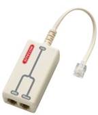 Figure 4 - PS (POTS Splitter - splitter). Description of the network. The main challenge facing the Alcatel 1000 ADSL access system is to provide fast access to the Internet and corporate LANs. This task is solved using a combined infrastructure consisting of at least four functional groups: - a small LAN at the subscriber's premises, - a communication network of the network operator that contains an access network, multiplexers, BB (Broad Band-broadband switch) and high-speed core network; - LAN at an ISP (Internet Service Provider) in the case when access to the Internet is performed in this way; - Enterprise LAN in a case when access to the corporate network is provided. Network architecture. Various technologies are used to provide end-to-end network architecture: - standard LAN technology between a personal computer and ANT (Ethernet II or IEEE 802.3); - ATM and ADSL technologies between ANT or PC-NIC (Network Interface Card) and ADSL- equipment on the CO side; - standard transport equipment between ASAM and support wAN (territorial network) using SDH / SONET or PDH; - BB switches / cross connectors in the core of the WAN core network; - having high performance and at the same time standard LAN - equipment in the ISP infrastructure and corporate LAN. The network architecture includes : Internet service provider, reference router, Internet, servers, access equipment, subscriber premises, subscriber, access network, small LAN, set-top box, splitter, corporate LAN infrastructure, division router, core network, separate personal computer. Network in subscriber premises. It can be either a separate personal computer or a small LAN containing up to 16 end systems. Interconnections between ANT and end systems are made using LAN equipment that meets the requirements of an Ethernet II or IEEE 802.3 interface. Since the ANT is equipped with a 25.6 Mbps ATMF interface, it is also possible to connect ATM equipment (STB, etc.). n.), with both interfaces, that is, Ethernet and ATMF, can be involved simultaneously. WAN and backbone network. Through the ASAM multiplexers, the core network and WAN connect subscribers to ISPs and corporate LANs.The main functions of these objects include: - transporting information within the WAN; - cross-linking information flows between individual users and ISPs and corporate LANs. ISP providers and corporate LANs . There are practically no fundamental differences between the ISP's local LAN and the LAN of a large corporation. In general, the structure of a LAN connected to a public communication network includes: - access communication servers (sometimes called VC bridges (Virtual Connection)); - IP backbone routers; - high-speed lAN networkfor example, with fiber optic connections (ATM FDDI interface (FiberDistributed Digital Interface interface)); - information servers; - communication servers of WAN trunks. An important aspect of this equipment is that it must be terminated with sets of protocols, exactly the same as those available in the subscriber premises. ADSL access subsystem. It is designed to implement the modern method of signal processing or modulation necessary to provide a connection over a twisted-pair subscriber pair with modem transport technology (ADSL modems). This modem technology is based on Discrete Multi-Tone DMT modulation - discrete multi-tone modulation, which is integrated into ASAM on the CO side and into ANT or PC-NIC on the subscriber side. ASAM multiplexer interfaces are equipped with so-called PS, which are compression devices and decompression of the frequency domains for ADSL and POTS signals. Partially external device PS is also used as part of the equipment located in the subscriber premises. The elements of the access network are managed through a (remote) centralized management object called AWS (ASAM WorkStation), which uses the Simple Network Management Protocol (SNMP) network). Information is exchanged between AWS and access network elements over dedicated connections intended for administration. An ADSL access subsystem can work with both CO and remote units. Remote ASAM equipment can either be directly connected to the ATM backbone network, or cascaded from the ASAM multiplexer located on the CO via a PDH interface. System architecture. The main building blocks of the global ADSL architecture are (See Figure 5): - ASAM for ADSL on the CO side; - ACU (Alarm Control Unit) (AACU -); - ADSE-A Extender (ADSL Serial Extender - Serial ADSL - Extender ); - ANT or PC-NIC and PS on the subscriber side; - Remote R-ASAM multiplexer (remote, remote) located deep in the network; - AWS network element manager. Inside, each SDH / SONET interface module is connected using two-way media transmission, with a number of associated ADSL-LT modules (Line Termination - linear termination), with the IQ Qualit bus y of Service Interface - a quality of service interface that provides a control interface for data transmitted over the direct and reverse channels. For docking with remote multiplex equipment (such as R-ASAM), it is also possible to provide linear PDH-LT terminations (DS3 / E3) or SDH-LT (STM1 or OC3c).
 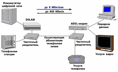 Figure 5 - Global ADSL architecture Global ADSL architecture: narrowband PBX (for example, PSTN networks), ADSL - subscriber, IQ bus, PBX building, twisted pair, subscriber premises, ATM.ASAM network. Using a number of interfaces (SDH STM1 or SONET OC3c), the ASAM multiplexer is located on the CO side and connected to a station that implements BB-ISDN ATM technology. The ASAM multiplexer modem interfaces are also equipped with so-called PS, which are the compression and decompression devices of the frequency domains for ADSL and POTS signals. The ACU provides a visual display of emergency situations and docking with the corresponding system located in the PBX building. Each cabinet has one ACU unit (up to 4 ACUs in a fully equipped ASAM multiplexer). Expander. It allows you to connect to the expansion line additional podstativy and, in order to protect equipment, duplicated. The transport system. The key part of the ADSL access subsystem is the "ADSL modem". To make multimedia connections based on ATM and Ethernet, a twisted pair is used between the subscriber equipment (ANT) and the equipment located in CO (ASAM). The ADSL system has two ADSL modems, one of which is on the CO side, and another in the subscriber's room. In combination, these subsystems provide a twisted pair bandwidth extension, which is the interconnecting medium. ANT. ANT equipment is located in subscriber premises. It provides the interface of a small subscriber LAN, a separate personal computer and / or STB (for multimedia purposes) with other LAN and / or ATM equipment on the other side. All services related to the docking are provided by the ADSL signal. PC-NIC. It is a PCI plug-in card (peripheral device interface), which is located in the subscriber room. It is no different from ANT in its functions, but it eliminates the need to have an additional Ethernet or ATMF.R-ASAM interface board. The ASAM remote multiplexer performs substantially the same functions as the usual one, however, it satisfies more stringent requirements in terms of design, power, and environmental conditions of operation. R-ASAM can be either autonomous or cascaded from ASAM located in CO. R-ASAM can be placed either in a street case or in CEV (Controlled Environment Vault - a camera with controlled climatic parameters). The maximum capacity of a standalone ASAM network multiplexer is 576 lines. In the case of cascading from CO, the maximum capacity (CO plus remote subscribers) remains unchanged — the same 576 lines. The network element manager. To manage the ADSL access subsystem, an AWS manager is provided that works via SNMP in an ATM channel located inside the bandwidth. AWS has a TL1 interface designed for a higher level OSS (Operation Support System) system. For the ADSL access subsystem, AWS provides control of active elements found in ASAM, R-ASAM, ANT blocks, or PC-NIC interface cards. 2.2 ASAM multiplexer - functional description ASAM architecture. In the ADSL access subsystem, ASAM is located on the CO side. Twisted pair and through the equipment, each subscriber connects to a broadband (BB) network and a narrowband (NB Narrow Band - narrowband) telephone exchange. In general, the ASAM multiplexer converts data from different subscribers into an ATM format. The ATM cells obtained as a result of this adaptation are summarized into one information flow and sent to the transport system of the connected BB-ATM network. ATM cells received from the BB-ATM network are decomposed according to the VPI / VCI identifier (VirtualPathIdentifier - virtual path identifier, VirtualChannelIdentifier - virtual channel identifier) and are broadcast to their original format on the external service interface. In addition, ASAM also functions OAM that ensures its proper operation. The main functions of ASAM include: - general-purpose functions; - compression / decomposition; - control (OAM); - NT functions; - TA (terminal adaptation) - functions; - branching functions (PS); - power supply functions. Network termination. Network Termination SANT (Synchronous ATM Network Termination-Synchronized Network ATM Termination) version D (SANT-D) connects the network transport system to the A1000 ADSL system and performs the functions associated with the physical and ATM layers. A networked digital transport system has a speed of 155.52 Mbps (SDHSTM1 / SONETOC3c). In the ASAM SANT-D multiplexer, the network end for the SDH / SONET information flow is 155.52 Mbps. It adapts ATM cells carried by the digital transmission system to the IQ bus and back. In addition, the SANT-D Network Termination provides features necessary for the operation and maintenance of ASAM. Finally, the SANT-D network termination provides an IQ bus extension, for which an appropriate interface is also provided. If you have 1 SANT-D network termination and 11 ADSE version A extenders (ADSE-A), you can manage twelve substives (12 substates x 12 LT x 4 lines = 576 lines). The SANT-D network termination is physically performed on the plug-in (double-European) printed circuit board, which is inserted into the ASAM multiplexer cabinet from the IQ bus side. IQ bus. It provides control and data exchange between NT and linear interfaces, that is, it is a device that compacts and decompresses the bit streams between them. IQ is a bus structure between SANT-D or ADSE-A and ADLT (ADSL Line Termination). The IQ bus has a way to route data along the forward and reverse channels, the synchronizer and control signals. The interface transfer rate is 155 Mbps. Transportation in the forward and reverse directions is performed using ATM cells, which are sent in frames consisting of 54 bytes. Sending in the forward and reverse directions is carried out on separate buses that carry 8-bit data. Physically, IQ is designed as a bus on a BPA (Backpanel Printed Board Assembly - back panel board) and permanently fixed in the ADSL cabinets as a motherboard. SANT-D or ADSE-A, ADLT and AACU cards are inserted into the appropriate BPA connectors. Accordingly, their mutual connections are made through the IQ bus. Terminal adaptation. ADLT converts ATM cells received from SANT-D and intended for the subscriber into DMT-modulated signals and vice versa and, therefore, works with the physical and ATM levels. Physically, the ADLT function is implemented on a single printed circuit board, in which there are 4 ADLT ports (4 subscriber connections). This card is inserted into the system (implementing IQ bus) ADSL card - cabinet. Also on the ADLT-card are implemented the control (OAM) functions for four ADLT-ports. PS splitter. On the subscriber line (twisted pair, going from the local PBX) analog POTS and ADSL signals are superimposed on each other, while both signals are frequency-multiplexed. In ASAM, ADSL and POTS signals are separated when passing in the opposite direction and combined when passing in the forward direction using special filters: - LPF which is transparent to POTS signals and attenuates ADSL signals; - HPF which on the way of ADSL signals prevents all disturbances from typical POTS signals (for example, dialing pulses, DC voltage and calling frequency). These special filters can be implemented using both passive and active filter elements. IQ interface. It connects the SANT-D and ADSE-A to the ASAM rear panel and consists of two buses: - IQD bus, intended for high-speed transmission (ATM cells) in the forward direction; - IQU bus, intended for high-speed transmission (ATM cells) in the reverse direction; - IQA (access) buses designed to control access to the IQU bus. The IQD and IQU buses transport ATM cells, each of which has a 5-octet header and a 48-octet information field. In addition, there is one idle octet before each cell. SANT-D encapsulates ATM cells in 54-octet slots and provides access to the IQ bus. Speed adaptation of 155.52 Mbit / s to speed of 152.64 Mbit / s (= 53/54 from 155.52 Mbit / s) is carried out by erasing the unfilled cells. This can be done because the maximum speed of valid ATM cells contained in the VC-4 is limited to 149.76 Mbit / s (= 26/27 from 155.52 Mbit / s). The IQA bus is designed to control access to the interface. with the return channel. It allows you to avoid "clashes" on the return channel bus and at the same time allows you to enter priorities at various levels for access by various LT objects. BPA system board. BPA (system board assembly) is a printed circuit board fixed on the back side of an ADSL equipment cabinet. The main functions of the motherboard are: - forming an IQ bus that provides SANT-D or ADSE-A connection to ADLT ports and ACU; provision of external interface connections for ACU; - connection of all active units to the station power bus at -48 V. External interfaces. Inside the ASAM multiplexer, there is one kind of transport: the SANT-D board is connected to the optical fiber and transmits data to the main and external substive. When it is necessary to improve the quality of service, availability and reliability, the SANT-D board and the incoming optical fiber are duplicated. Only one SANT-D card is active at a time. In the expansion substatives, one expander card is used as a buffer for different signals. In each substive, the extenders are duplicated. Thus, under the control of the SANT-D board there are several ASAM buses: - in the main substable; - IQ bus; - special lines; - serial ACU interface in the expansion substates (via the expansion interface). Optical transport interface (STM1 / STS3c). SANT-D is the terminal of one SDH STM1 / OC3c channel at 155 Mbps. Transmission on these connections is carried out using a single-mode (also called single-mode) optical fiber, which ends in OTM (Optical Transceiver Module - optical transceiver module). Subscriber line interface. The interface is a connection from the ADLT to the ANT block located in the subscriber premises. The subscriber line interface provides the passage of conventional telephony signals, which are frequency-multiplexed with ADSL / ATM signals going in the forward and reverse directions. This interface connects the ADLT to the ANT via a twisted pair access network. For the connection using a regular telephone wire. A sequential expansion interface. IQ bus signals from the first main shelf, in which the SANT-D board is located, can be distributed to 11 slave shelves, each of which has a serial expander ADSE-A. The serial expansion interface is the connecting link between the SANT-D card and the ADSE-A boards. The SANT-D card has one output connector for serial expansion, and the ADSE-A card has two. All connectors are located in the front of the cabinet. Service interface. It is provided on the SANT-D board. Access to this interface is through a connector located in front of the ACU. Internal interfaces. IQ interface. The ADLT card is docked to the SANT-D or ADSE-A card via the IQ bus. If the SANT-D card has only one SDH STM1 interface, then for connecting ADLT cards, the number of which can go up to 144, and 11 ADSE-A boards, there is only one IQ bus. All ADSE-A boards have to share the available bandwidth (155 Mbps) of the IQ bus. There are two IQ bus positions on the SANT-D board, since on this board, you can switch to 2 STM1 connections at any time. MBC interface. The SANT-D board provides the ability to selectively turn on / off the power of each of the ADLT terminals connected to the IQ bus. The physical location of the BPA and PBA. Each BPA motherboard and each PBA (Printed Board Assembly) node inside the CO is assigned a unique physical location number. This number has 32 bits and is represented as ID0 ... ID31. These bits have the following purpose. The 5-bit number identifies the position of each PBA node on the system board. This number is presented as ID0 ... ID4 and characterizes the slot number (1 ... 13) PBA on the motherboard. This number is hard-wired into the system board and can be read by the ADLT / SANT-D / ADSE-A card through the pins on its system board connector. Multiplexer power supply. The ASAM multiplexer is powered from a station source at -48 or -60 V. 2.3 Transport system Services and transmission rates. Transport ADSL - system provides two-way communication over a single twisted pair without any repeaters. The ADSL system combines DMT technology and ATM transfer mode. The result of this combination, in particular, are: - the ability to provide an effective combination of different services, characterized by different bandwidths and traffic characteristics, and the maximum physical speed that can be obtained from a DMT modem; - automatic determination of the maximum physical speed during the modem initialization process ( taking into account the specified noise limit level and within the limits imposed on the transmit power spectral density). In this case, the service management system sets, depending on the customer service profile, the correct value of the linear velocity, thereby reaching the optimum level of noise and / or minimizing the transmission power. All this makes it possible to differentiate the quality of service, for example, by offering maximum speeds at a higher price or by providing guaranteed speed; - transfer rates can be linearly selected to the physically maximum possible, and also set for each individual user; - combined use of technologies DMT and ATM allows the system to initialize and operate at very low speeds in those, for example, cases where lines are unstable or when many errors in cable linear structures. Due to its inherent reliability, the system will be initialized even in extremely adverse conditions, informing the network management system of this. In this case, the operator can download the ADSL parameters and take the necessary measures; - decoupling the speeds of ATM cells (by inserting or extracting empty or undefined cells) makes it possible to transmit at any speed up to the maximum achievable on the ADSL connection. Digital ADSL transmitting capacity - The system is asymmetric in the sense that the speeds in the forward and reverse directions are different from each other: - The speed in the forward direction can vary from 0.25 to 8.0 Mbit / s, with the speed parameter and equal to 32 Kbps; - the speed in the opposite direction can vary from 35 Kbps to 1 Mbps, while it depends on the supported bilateral services and characteristics of the loop. 2.4 ANT Functional Description General information. The ANT equipment is located in the subscriber premises and provides the docking of the subscriber TE with the incoming subscriber line (the twisted pair through which the ADSL signal is transmitted). In the forward direction, the ANT block is the end for the signal (DMT-modulated ATM cells) in the ADSL channel, received from CO on the incoming twisted pair. It demodulates the signal and converts the ATM cells contained in it into a digital bit stream that can be sent to the subscriber TE. In the opposite direction, the ANT inserts the ATM cells received from the subscriber TE into their stream and generates a signal (DMT-modulated ATM cells ) An ADSL channel, which is routed to the CO over the incoming twisted-pair subscriber. There are 3 types of Speed Touch DSL modems: - Speed Touch PC-NIC is a built-in modem (board), oriented mainly to private users. Point-to-Point connection (PPP); - Speed Touch Home - external modem, targeted at both private users and low-capacity LAN users (small office, home office). It has a built-in Ethernet port and a function “ transparent bridge ”(Bridge); - Speed Touch Pro is an external modem designed for users of large LANs. Functions are similar to ST Home, and it can also function as a router.
 3. Calculation of ADSL equipment 3.1 Development of the design of the projected access network When calculating the access network based on ADSL equipment, we will use the contract proposal received from company N to organize high-speed Internet access for 164 subscribers. The choice of equipment, especially at the initial stage, is one of the most painful problems for those whose decisions determine the fate of the project in the long term. To implement this project, it was decided to use hardware and software Alcatel, a leader in the ADSL device market. In order to effectively address the challenges that customers put before us, and the subsequent support of projects, Alcatel has developed the All-in-One concept, which is being implemented today in the Russian market. Its essence lies in the fact that the customer is provided with a comprehensive package of services, ranging from consulting on developing a business plan to equipment maintenance and system management during operation. This approach of the company is based on a deep understanding of the customers' business. As part of the All-in-One, the customer interacts with one integrated global company. The support service offers the same level of service throughout the world, and in each country there is a single phone number for access to it. The full package of All-in-One services includes planning and development, development, operation and support of systems. For each of these areas, Alcatel has created the appropriate services. The planning and development service provides an expert assessment of the existing communication system and determines the type of project being developed, the implementation of which will maximize the efficiency and profitability of the customer’s communication systems and networks. The development service covers all stages of implementation necessary for installing and launching communication systems and networks in accordance with customer expectations. It also provides for the training of its personnel and qualified assistance in accompanying a high-tech system directly on the site of its installation. The operation service works in the mode of immediate response and helps the customer’s staff to solve current technical problems in the process of maintaining systems and networks. The support service offers expert assistance in case of technical problems. Based on on-line diagnostics, experts decide to replace, for example, the failed component or the entire communication system if the infrastructure has suffered from a natural disaster - fire, flood, etc. p. Essential when building an ADSL network is the correct combination of hardware and software tools . Alcatel, along with a full-featured set of equipment, offers a resource management platform. This platform includes a set of tools that allow you to solve technological problems of network management, and service management tools, which, strictly speaking, determines all the variety of opportunities provided by the operator to solve problems of his business. The ADSL system consists of two parts, the first of which (on the CO side) is called ASAM, (ATMSubscriberAccessMultiplexer - ATM - subscriber access multiplexer), and the second (on the subscriber side) - CPE (Customer Premises Equipment - equipment at the customer's premises). CPE, in turn, includes PS (POTS Splitter - splitter) and ANT (ADSL NetworkTermination (unit) - network ADSL termination). As the hub equipment of the communication operator on the projected access network, 6 AAMA ASAM multiplexers are used , which are installed in crosses PBX (CO). ASAM multiplexer configuration. 1 and 3 ASAM: - ETSI UT-9 rack, which is a multiplexer housing; - SANT-D board, which provides optical access to the digital SDH transmission system at 155.52 Mb / s and adapts to this ATM system cells carried along the IQ bus in both directions. In addition, this board provides the functions necessary for the operation and maintenance of the ASAM multiplexer; - the ACU board provides a visual display of emergency situations and docking with the corresponding system located in the PBX building; - ADLT boards of 7 pieces, each of which is connected 4 ADSL modems, i.e. in general, 28 pieces, 14 of which are modems of the ST PC NIC family; 13 - ST Home family modems; 1 - ST PRO family modem; - splitters of 7 pieces each, where ADSL and POTS are separated - external splitters are located in the subscriber room and are connected to the twisted pair cable coming from the ADSL service provider.2,4,5 ASAM multiplexers in composition the hardware is identical to the 1st and 3rd multiplexers. 6 ASAM multiplexer is characterized by the presence of 6 ADLT cards and 6 splitter cards, as well as 12 ADSL modems of the ST PC NIC family and the ST Home family are connected to it. The 2nd and 4th ASAM multiplexers are connected to 13 of which are modems of the ST PC NIC family; 14 - ST Home family modems; 1 - ST PRO family modem. 14 ADSL modems of the ST PC NIC family and the ST Home family are connected to the 5th multiplexer. Alcatel has suggested that the customer use 3 types of ADSL modems for connecting individual users, local networks, and subscribers SOHO (SmallOffice / HomeOffice, i.e. representatives of small businesses and home users). For individual users, the internal modems of the Speed Touch PC family (PC NIC) are installed. For SOHO subscribers, Internet access is organized using ADSL modems of the SpeedTouchHome family. Local networks are connected using ADSL modems of the Speed Touch Pro family. network access is carried out through a remote centralized management facility called AWS (ADSL Work Station), which uses the SNMP.ASAM protocol to connect equipment to an existing transport network. tnoj SDH network through the already established ATM - the customer switch through channels STM-1. The access multiplexer accepts cell streams from individual subscriber devices and multiplexes them for further transport in the "upstream" direction. Then, ATM switches direct each stream to its destination. Recovery of packets in the form in which they were generated by the sending station is performed by the trunk router or server remote accessinstalled at the entrance to the network of the Internet-provider or to the corporate network. These devices terminate that encapsulation level in the used protocol stack, which was activated by the user equipment, and then sends the recovered packets to the recipients. In addition, their duties often include identifying users, assigning IP addresses and changing the degree of use of network resources. The global Internet is accessed via an X.1000 access server (A7410), which connects to an ATM switch via STM-1. To implement the project, it is required to install 6 ASAM multiplexers to which 164 modems are connected: - 80 PC NIC modems; - 80 HOME modems; - 4 PRO modems, and also 160 splitters (no splitters are used when connecting local networks). Thus, a general summary equipment which will be installed on the access network is presented in Table 2. Table 2 Installed equipment
| Description | amount |
| basic configuration of operator equipment | |
| Rack ETSI UT-9 2200mm 48VDC | 6 |
| fees | |
| SANT-D, STM-1 | 6 |
| Alarm Control Unit (AACU) | 6 |
| ADLT | 41 |
| 41 | |
| basic configuration of client equipment | |
| Modem Speed Touch PC (PC NIC) | 80 |
| Modem Speed Touch Home | 80 |
| Modem Speed Touch Pro | 4 |
| Splitters (on the subscriber side) | |
| Passive POTS splitter 600 ohm | 160 |
| basic configuration cables | |
| CableMDF-ASAM 24 pair 25 meter | 6 |
| Optical cable | 6 |
| ADSL network management system | |
| (AWS) Oracle Server V7.3.2.2.0 RTU (8 conc. Users) | 1 |
| BYNM Expert 1390 Management SW | 1 |
| License AWS License fee per user (including MIB fee) | 164 |
| System units and boards | |
| X1000 shelf (includes fan, clock and alarm modules) | 1 |
| Power Supply 500 Watts DC | 2 |
| System Control Module, Model 120 | 1 |
| 3 WAN + 1 Ethernet | 2 |
| ATM Line Interface with single OC-3 Single mode IH | 1 |
| DC Fuse Panel (Hendry) | 1 |
| Switch Software, Release 2.2 | 1 |
3.2 Calculation of bandwidth for the projected access network Depending on the class of service, connected subscribers may be provided with either guaranteed bandwidth (CBR) or non-guaranteed (UBR). Service classes contain a number of parameters that determine the quality of service guarantees. There are several classes of service - CBR, VBR, UBR and ABR (appeared recently). Quality of service guarantees can determine the minimum level of available bandwidth and cell delay limits and cell loss probabilities are given in Table 2.1. Table 3.1 Comparison of two classes of service
The CBR service (constant bit rate, service with a constant bit rate) is the simplest class of service. When a network application establishes a CBR connection, it orders peak cell rate (PCR), which is the maximum speed that a connection can sustain without losing a cell. Then the data is transmitted over this connection with the requested speed - no more and, in most cases, no less. Any traffic transmitted by the station at a higher speed can be simply discarded by the network, and the transmission of traffic by the network at a speed lower than the one ordered will not satisfy the application. CBR connections must ensure throughput with minimal cell loss and low cell transfer delay changes. When an application orders a CBR service, it requires that the cell's transmission delay limit be met. CBR service is designed specifically for voice and video in real time. For CBR connections, there are no specific data transfer speed limits, and each virtual connection can request different constant data transfer rates. The network must reserve the full bandwidth requested by a particular connection. Unlike CBR, the UBR service (unspecified bit rate) does not determine either the bit rate, the traffic parameters, or the quality of the service. The UBR service offers only delivery "whenever possible", without guarantees for the loss of cells, the delay of cells or the limits of the change in delay. Designed specifically to be able to exceed bandwidth, the UBR service is an adequate solution for those unpredictable “explosive” applications that are not ready to accept the traffic parameters. At the same time, UBR allows for maximum throughput when multiple data streams are added together with load peaks that are separated in time. The main drawbacks of the UBR approach are the lack of flow control and the inability to take other types of traffic into account. When the network becomes congested, UBR connections continue to transfer data. Network switches can buffer some of the incoming traffic cells, but at some point the buffers overflow and the cells are lost. And since UBR connections did not enter into any agreement with the network about traffic management, their cells are discarded first. The loss of UBR cells can be so great that the “yield” of cells can fall below 50%, which is completely unacceptable. To eliminate this disadvantage, Alcatel's ASAM multiplexers allow the use of UBR + mode, which allows the subscriber to set the minimum guaranteed transmission rate - MCR. Typically, traffic characteristics are defined as typical subscriber profiles. Assume that for the largest users with their own LAN, Profile 1 will be used, which will provide the CBR service class and transfer rate to the network not lower than 1 Mbps, and receive information from the network - 8 Mbps. For users with small LANs, profile 2 will be installed, which will provide the UBR + service class and guaranteed network transfer rate of at least 256 Kbps, and guaranteed transfer rate from the network of at least 512 Kbps, respectively, maximum transfer rates of 512 Kbps and receiving 1024 kbps. Individual users will be set to profile 3, which will provide the UBR + service class and guaranteed network transfer rate of at least 128 Kbps, and guaranteed transfer rate from the network of at least 256 Kbps, respectively, the maximum transfer rate of 256 Kbps and receive 512 Kbps. The user type determines the type of ADSL modem to be installed. In accordance with the customer's request, 80 PC-NIC modems (individual users), 80 Home modems (small LAN) and 4 PRO modems (large LAN) will be installed on the network. Consequently, profile 1 will be installed for subscribers with PRO modems, profile 2 will be installed for subscribers with Home modems, profile 3 will be installed for subscribers with PC-NIC modems. At the first stage of implementation of the access network, the mode of permanent (non-switched) virtual connections will be used i.e. each user will be assigned a fixed VP / VC. Determining the correspondence between the total subscriber speeds and available bandwidth is based on the following conditions: 1. The maximum total speed of all CBR subscribers, together with the sum of guaranteed minimum speeds of all UBR + subscribers, should not exceed the effective bandwidth of the transmission medium used (in our case, STM -1), where STM-1 is the total payload of a valid ATM cell in STM1 C-4 is 155.52 * 26: 27 = 149.76 Mbps.) 2. The sum of the maximum (non-guaranteed) soon Tei transmission subscribers all UBR + service class must not exceed the available transmission system bandwidth, multiplied by the load factor (MCR - minimum bandwidth guaranteed for each PVC or SVC. This rate (in bits per second) is chosen by the subscriber in accordance with the amount of data that he is going to transmit over the network, and is guaranteed by the operator. If packet packets do not exceed the speed of the subscriber connection port and the network bandwidth is currently free, the subscriber may exceed the agreed MCR value. The rate at which a subscriber sends data when there is enough bandwidth is called the oversubscription rate. The value of the oversubscription coefficient can be from 2 to 6. UBR max<= Kubr * B, (3) где Kubr – коэффициент перегрузки имеющейся пропускной способности (Kubr = 400%);B – пропускная способность.Произведем расчет пропускной способности для 1-го мультиплексора ASAM. В соответствии со схемой в него включены 14 модемов PC-NIC (профиль 3), 13 – модемов ST Home (профиль 2) и 1 модем ST Pro (профиль 1). Таким образом, суммарная гарантированная скорость на NT – интерфейсе этого мультиплексора в нисходящем потоке составляет:- для одного модема ST Pro - 8 Мбит/с;- для 13 модемов ST Home - 13 х 512=6,656 Мбит/с;- для 14 модемов ST PC-NIC - 14x 256 = 3,584 Мбит/с;- общая гарантированная скорость 18,240 Мбит/с.Таким образом, суммарная гарантированная скорость значительно меньше имеющейся пропускной способности среды передачи: 18,240< 149,76х 0,95 = 142,272 Мбит/с.Произведем расчет суммы максимальных негарантированных скоростей для абонентов с классом обслуживания UBR+:- для 13 модемов ST Home - 13x1,024 = 13,312 Мбит/с;- для 14 модемов ST PC-NIC - 14x512 = 7,168 Мбит/с;- суммарная максимальная скорость - 20,480 Мбит/с.Проверим выполнение условия 2 для нашего случая, для этого определим пропускную способность, оставшуюся на негарантированную передачу: 142,272 – 18,240 = 124,032 Мбит/с. Как видно из приведенных вычислений оставшаяся полоса пропускания больше требуемой суммарной максимальной скорости для негарантированного трафика UBR+.Таким образом, для рассмотренного мультиплексора полностью выполняются условия 1 и 2. Поскольку число и типы абонентов, подключенных к остальным мультиплексорам не превышают число абонентов в 1-ом мультиплексоре, то пропускной способности подключенных к ним трактов STM-1 вполне достаточно, для обеспечения всех абонентов необходимым качеством передачи данных.Поскольку все абоненты, указанные на схеме, требуют выхода в сеть Интернет и на первом этапе используется режим полупостоянных соединений, тем самым узким местом в сети доступа является поток STM 1, связывающий АТМ – коммутатор с сервером доступа в Интернет.Проведем аналогичные расчеты для этого интерфейса с учетом условий 1 и 2. Таким образом, суммарная гарантированная скорость на этом интерфейсе в нисходящем потоке составляет:- для 4-х модемов ST Pro - 8х4 =32 Мбит/с;- для 80 модемов ST Home - 80 х 512=40,960 Мбит/с;- для 80 модемов ST PC-NIC - 80x 256 = 20,480 Мбит/с;- общая гарантированная скорость - 93,440 Мбит/с.Таким образом, суммарная гарантированная скорость меньше имеющейся пропускной способности среды передачи: 93,440 < 149,76 х 0,95 = 142,272 Мбит/с.Произведем расчет суммы максимальных негарантированных скоростей для абонентов с классом обслуживания UBR+:- для 80 модемов ST Home - 80x1,024 = 81,92 Мбит/с;- для 80 модемов ST PC-NIC - 80x512 = 40,960 Мбит/с;- суммарная максимальная скорость - 122,880 Мбит/с.Проверим выполнение условия 2 для нашего случая, для этого определим пропускную способность, оставшуюся на негарантированную передачу: 142,272 –93,440 = 48,832 Мбит/с. С учетом коэффициента допустимой перегрузки Kubr = 400% получим: 48,832 * 4 = 195,328 Мбит/с > 122.880 Mbps. Thus, the sum of maximum speeds for all subscribers of the UBR + class does not exceed the calculated value of the available capacity, taking into account the calculated value of the overload coefficient, i.e. Condition 2 is also fulfilled for the interface in question. The calculations performed show that the chosen option for constructing an access network fully satisfies the requirements for the load transmission of the designed network.
4. Justification of the feasibility of a design solution In recent years, the growth in the volume of information transmission has led to the fact that there is a shortage of bandwidth access channels to existing networks. If at the corporate levels this problem is partially solved (by renting high-speed transmission channels), then in the residential sector and in the small business sector these problems exist. Today, the main way that end users interact with private networks and public networks is access using a telephone line and modems, devices that provide digital information transmission over subscriber analog telephone lines. The speed of such communication is small, the maximum speed can reach 56 Kbps. This is still enough for access to the Internet, but the saturation of pages with graphics and video, large volumes email and documents in the near future will again raise the question of ways to further increase bandwidth. Currently, the most promising technology is ADSL (Asymmetric Digital Subscriber Line). This is a new modem technology that turns standard subscriber telephone analog lines into high-speed access lines. ADSL technology allows you to transfer information to the subscriber at speeds up to 8 Mbps. In the opposite direction, the speed is up to 1 Mbit / s. This is due to the fact that the entire modern spectrum of network services assumes a very insignificant transmission rate from the subscriber. For example, to get MPEG-1 movies, a bandwidth of 1.5 Mbps is required. For service information transmitted from the subscriber, 64 -128 Kbit / s is quite enough. The rapid growth in the number of Internet users, observed recently, both in the whole world and in Russia, gives reason to look at the prospects of the Russian ADSL market very optimistically. This optimism is shared by providers that are starting to deploy ADSL access networks. Today, the number of Russian Internet users is estimated at 1.95 million people (according to Dataquest). However, due to the lack of a clear definition of the term “Internet user”, this and other similar assessments should be perceived with a certain degree of skepticism. The frequently mentioned figure of 1.5-2 million cannot be regarded as absolute, since it can give rise to a distorted view. For example, according to the GfK MR Institute for Marketing and Social Research, which studies the Russian part of the Internet on the basis of representative surveys of the population of Russia over the age of 16, in July 2000, "... access to the World Wide Web was about 6 million Russians (5 , 5%), but only 24% of them (approximately 1.5 million) used this access more or less regularly (at least once a month) ”(“ Telecom Forum ”from 10.29.00). What is once a month in terms of profit? If the duration of work in the network on average is 4-5 hours, then at the prices for dial-up access of $ 1 per hour, $ 50-60 per year is obtained. Of course, the real interest for the provider (for this indicator) is represented by those customers who provide an order of magnitude higher income. The number of “effective” users in Russia in 2000 (we believe that the effective subscriber spends at least 20 hours per month on the Web) is estimated at the level of 350-450 thousand. Such a conservative estimate allows us to predict that the rapid growth of the subscriber base in the medium term, despite the low level of computerization and low incomes of the population, will continue. In the Moscow market of dial-up access in 2000, there was an increase in the average monthly load of the modem pool at the level of 5-6% per month, which confirms this assumption (Alcatel estimate based on data from the Russian Express company). This allows us to expect an increase in the number of effective Internet users, including broadband access subscribers. Thus, it can be argued that in Russia, as well as around the world (albeit adjusted for Russian specifics), there is a shift in the provision of Internet services side of broadband systems. One of the main problems in organizing high-speed Internet access based on asymmetric digital subscriber line technology (ADSL) is the question of choosing equipment that, especially at the initial stage, is Oboy is one of the most painful problems for those whose decisions determine the fate of the project in the long term. To implement the project to build an ADSL network to access the global Internet, it was decided to analyze the possibility of using Alcatel hardware and software or equipment from Cisco Systems. The analysis is based on the hierarchy analysis method (MAI). The hierarchy analysis method is a mathematical tool that is designed to solve multi-criteria optimization problems, which, unlike traditional methods, allows you to make a compromise solution. MAI is a systematic procedure for hierarchical representation of the elements that determine the essence Problems. The method consists in decomposing the problem into more and more simple components and further processing the sequence of judgments of the decision maker by pairwise comparisons. As a result, the relative degree (intensity) of interaction of elements in the hierarchy can be expressed. These judgments are then expressed numerically. AHI includes procedures for synthesizing multiple judgments, prioritizing criteria, and finding alternative solutions. The values obtained in this way are estimates in the scale of relations and correspond to the so-called hard estimates. Comparative analysis of ADSL equipment. To select the most suitable ADSL equipment for the implementation of this project, we will compare two possible hardware and software options that can be used to design this broadband access network: ADSL equipment from Alcatel and Cisco Systems. Possible options: 1 Variant - ASS 1000 ADSL multiplexers and Alcatel subscriber equipment; Variant 2 - Cisco 61xx / 62xx series multiplexers and ADSL modems by Cisco Systems. Comparison of these systems will be carried out according to the following indicators: 1 cost; 2 reliability; 3 ease of operation; 4 security of the transmitted data; 5 flexibility of equipment control; 6 implementation of bridging / routing functions; 7 multiprotocol; support of various network interfaces; 8 digital transmitting capacity of the ADSL system; 9 adaptation of ASAM / DSLAM data; management of data transfer; 10 advertising policy of companies. The solution of the task (system selection) using the MAI is carried out in several stages. Representation of a task in a hierarchical form. Choice of ADSL equipment: Level 1 (overall goal); Level 2 (criterion): cost, reliability, ease of operation, ensuring the security of transmitted data, flexibility of equipment management, implementation of routing bridging functions, advertising policy of companies, data adaptation in ASAM and DSLAM, digital data transfer control; level 3 (alternative); Prioritization of criteria. To establish the priority of criteria, pairwise comparison of criteria with respect to a common goal is carried out, the results of pairwise comparison are entered in the matrix. One or another assessment (from 1 to 9) of relative importance is placed in each cell of the matrix. The relative importance of the left elements of the matrix with the elements at the top is compared. Therefore, if the element on the left is more important than the element at the top, then an integer is entered into the cell; otherwise, the reverse number. The relative importance of any element that is comparable to itself is 1. Table 3 shows the scale of estimates of the intensity of relative importance. Table 3 Scale of estimates of the intensity of relative importance
The calculation of the priority vectors is performed in the following sequence. First, the elements in each row of the matrix are multiplied, and the root of the nth power is extracted, where n is the number of elements in the row. The obtained values are called the components of the normalized vector of priorities, the number of components equals the number of rows. Then the column of numbers obtained in this way is normalized by dividing each number by the sum of all numbers, which ultimately is a vector of priorities. The consistency index (CI) in the matrix can be approximately obtained as follows : - each judgment column is summed, then the sum of the first column is multiplied by the magnitude of the first component of the normalized vector of priorities, the sum of the second column is and the second component and so forth; -.. determined coherence index where n-number of the compared elements. The consistency index provides information on the degree of numerical and ordinal consistency violation; the correlation ratio (OS) is determined by dividing the IP by the number corresponding to a random matched matrix of the same order (for a 10th order matrix, random consistency is 1.49). The value of the OS must be of the order of 10% or less to be acceptable. In our case, the consistency ratio is much less than 10% and does not go beyond the permissible limits. This means that the matrix is consistent, and there is no need to revise judgments. Determining local priorities. Matrixes of local priorities, similar to the priority matrix of criteria relative to the main goal, are compiled for pairwise comparison of alternatives to each of the criteria. Matrices of ADSL equipment preference estimates for different The criteria are given in Tables 3.1 ... 3.10: Table 3.1. Matrix of pairwise comparisons for level 3 in the parameter “Cost”
Table 3.10 Matrix of pairwise comparisons for level 3 on the parameter “Advertising policy of companies”
| Alcatel | 1 | 3 | 1,732 | 0,75 |
| Cisco Systems | 1/3 | 1 | 0,577 | 0,25 |
| IP = 0 |
Definition of global priorities. The next step is to apply the principle of synthesis. For each alternative, the sum of the local priority works of this alternative is found, for each of the criteria for the priority of the corresponding criterion in relation to the higher level. The preferred option is the 1st option, that is, the design of an access network to the global Internet network based on the Alsatel ADSL equipment. As a result of the comparisons conducted in this section, the following conclusions can be drawn: - Based on the comparative analysis carried out using the hierarchy analysis method (MAI), it was concluded that ADSL equipment by Alcatel advantageous to use the access network compared to ADSL Cisco company equipment (meaningfully global priorities) - Alcatel company requires less capital expenditures and operating costs.
5. The economic part In the economic part of the graduation project, the cost is calculated software productThe cost price of a software product was made up of the following articles. 1) Material costs are given in Table 4. Table 4 Material costs) Total: Essential WFD = ТЗ / п + Bonus + Dvr. (9)
Basic system = 2414.45 + 724.335 + 289.734 = 3428.519 rubles.
e) Dop.FZP = 10% * Basic. ZPZP (10)
Additional FZP = 3428.519 * 0.1 = 342.851 rub. G) Total: FZP = Basic FZP + Additional FZP (11) FZP = 3428.519 + 342.851 = 3771.370 rubles. 4) Deductions for social needs of 26% of the wage bill of unified social tax = 0.26 * 3771.37 = 980,556 rubles. (12) 5) Overhead costs 60% of Basic Draft Cost. = 0.6 * 3428.519 = 2057.111 rubles. (13) Practical relevance: With the use of this ADSL technology on a subscriber telephone line, it has been possible to transform a subscriber cable network into a part of a high-speed data transmission network. Significantly increased the speed of transmission and reception of data. In our city, ADSL technology has taken one of the first places to provide high-speed Internet access. At the moment in Novocheboksarsk there are already more than 1,800 people using ADSL technology.
6. Ecology and life safety 6.1 Impact of the monitor on the human body Among the various physical environmental factors that can adversely affect humans and biological objects, non-ionizing nature electromagnetic fields, especially those related to radio frequency radiation, are more complex. Here, a closed production cycle without the release of a polluting factor into the environment is unacceptable, since the unique ability of radio waves to propagate over long distances is used. For the same reason, radiation shielding and replacement of the toxic factor with another less toxic factor is unacceptable. The inevitability of the effects of electromagnetic radiation (EMR) on the population and the surrounding wildlife has become a tribute to modern technical progress and the increasing use of television and radio broadcasting, radio communications and radar, the use of microwave radiating devices and technologies, etc. And although some sewage radiation is possible, which reduces unwanted exposure of the population, and regulation of radiating devices during operation, further technical progress still increases the likelihood of exposure to EMR on humans. The possibility of an adverse effect on the human body of electromagnetic fields (EMF) was drawn attention in the late 40s. As a result of a survey of people working in conditions of exposure to EMF of considerable intensity, it was shown that the nervous and cardiovascular systems are the most sensitive to this effect. Changes in hematopoiesis, disorders of the endocrine system, metabolic processes, and diseases of the organs of sight are described. Under conditions of prolonged occupational exposure with a periodic increase in maximum permissible levels (PDL), some people noted functional changes in the digestive organs, which are reflected in changes in the secretion of gastric juice acidity. also in the phenomena of intestinal dyskinesia. Functional changes on the part of the endocrine system were also revealed: an increase in the functional activity of the thyroid gland, a change in the nature of the sugar curve, etc. In recent years, there are reports of the possibility of EMR induction of malignant diseases. Still a few data still indicate that the greatest number of cases are in tumors of the hematopoietic tissues and in leukemia in particular. Video displays of personal computers (VDPK) are used during the daily activities of millions of employees around the world. Computerization in our country takes a wide range, and many hundreds of thousands of people spend most of the working day behind the display screen. Along with the recognition of the undoubted benefits of the use of computer technology causes concern for their health and numerous complaints from PC users. There are statistics according to which people working with computers are more restless, suspicious, more often avoid communication, as well as mistrustful, irritable, prone to increased self-esteem, arrogant, fix attention to failures. 6.2 Methods of protection against electromagnetic radiation Personal computer (PC) has taken a strong place in the activities of many people. Now it is impossible to imagine full-fledged work in enterprises, in private business, and in the process of learning without a PC. But all this "can not but cause concern about their harmful influence on the health of users. Underestimating the features of working with displays, in addition to reducing the reliability and efficiency of working with them, leads to significant health problems. The implementation of recommendations for the operation of computers can significantly reduce the harmful effects of computers in operation. First of all, security when working with a PC can be ensured by rational placement of computers in the premises, proper organization of the users' working day, as well as through the use of contrast enhancement tools and protection from glare on the screen, electromagnetic radiation and the electrostatic field. so that the display screen is 50 (not closer) from the user's eyes - 70 cm. Rest modes for working with PCs, according to, depend on the category of work activity. All work with PCs are divided into three categories: - episodic reading and entering information no more than 2 hours for an 8-hour work shift; - reading information or creative work no more than 4 hours for an 8-hour shift; - reading information or creative work for more than 4 hours in an 8-hour shift. If more than one computer is operated in the room, then it should be noted that radiation from other PCs may affect the user of one computer, primarily from the side PCs, as well as back of the display. Considering that radiation from the side of the display screen can be protected by using special filters, it is necessary that the user is placed at least 1 m away from the side and back walls of other displays. It is recommended to install full protection protection filters on monitors that provide almost complete protection from all harmful effects of the monitor in the electromagnetic spectrum and allow to reduce the glare from the cathode ray tube, as well as improve the readability of characters.
6.3 Fire Safety
To solve the problems of fire safety, we must first determine and justify the category of the room.
One of the most important tasks of fire protection is to protect the premises from damage and ensure their sufficient strength in conditions of exposure to high temperatures in a fire. Given the high cost of electronic equipment, as well as the category of its fire hazard, the building should be 1 and 2 degrees of fire resistance.
For the manufacture of building structures are used, as a rule, brick, reinforced concrete, glass, metal and other non-combustible materials. The use of wood should be limited, and if used, it is necessary to impregnate it with flame retardants. It is also necessary to provide fire barriers.
The fire extinguishing agents for small fires include: fire rods, internal fire pipelines, fire extinguishers, dry sand, asbestos blankets, etc.
In buildings, fireplugs are installed in the corridors, on platforms and entrances. Water is used to extinguish fires in the premises of PC users, the archive and ancillary and service premises. The use of water in rooms with PCs, storage facilities for information carriers, premises of instrumentation due to the danger of damage or complete failure of expensive equipment is possible in exceptional cases when a fire takes on alarmingly large dimensions. The amount of water should be minimal, and the PC must be protected from water, covering them with a tarpaulin or canvas. Fire extinguishers are widely used to extinguish fires in the initial stages.
In rooms with a PC, carbon dioxide fire extinguishers are used, the advantage of which is the high efficiency of extinguishing a fire, the safety of electronic equipment, the dielectric properties of carbon dioxide, which makes it possible to use these fire extinguishers even if the electrical installation is not immediately de-energized.
All computer rooms must be equipped with stationary automatic fire extinguishing installations. It is most expedient to use gas fire extinguishing installations. The action is based on the rapid filling of the room with a fire extinguishing gas substance with a sharp liquefaction of the oxygen content in the air.
6.4 Electrical Safety
The modern level of technical progress is impossible without the widespread introduction of electrical equipment, which in turn makes it necessary to constantly improve the requirements for its safe maintenance and protection.
Work in the field of electrical safety should be based on a well-thought-out, precise, specific system of measures ensuring the full and accurate implementation of the “Rules for the technical operation of electrical installations of consumers” and the “Rules of safety in the operation of electrical installations for consumers”. Heads of electrical facilities should pay particular attention to the strictest compliance with the requirements of these rules regarding the maintenance and operation of electrical networks and stations, including switchboards, where, according to statistics, accidents occur most often. A large number of accidents occur during maintenance and repairs of electric drives, control gears, electric lighting, welding machines, electrified vehicles, electrical equipment, lifting and transport mechanisms, hand-held portable tools, and high-frequency installations.
Electrical installations according to voltage are divided into two groups: voltages up to 1000 V and over 1000 V. Practice shows that electrical injuries, as mentioned above, more often occur in electrical installations with voltages up to 1000 V.
Most accidents occur due to the low level of work organization, gross violations of the rules, including:
Directly touching open live parts and wires
Touching live parts, the insulation of which is damaged.
Touching the metallic parts of the equipment, accidentally energized.
Contact with current-carrying parts using items with low insulation resistance.
Absence or violation of protective earth.
Incorrect supply voltage during repairs or inspections.
The effects of electric current through the arc.
Effects of step voltage, etc.
An electrician was injured in the small casting section of the iron foundry, which, on the instructions of the master, replaced the burned out electric bulbs. For this purpose, he used a ladder, supported by replacing each lamp with the starting equipment of an electric hoist moving along a closed ellipsoid monorail. In this case, the voltage from the trolls was turned off each time the lamp was replaced and turned on again to move the hoist to the next lamp. During the replacement of the next lamp, the electrician took hold of the trolls who were under voltage this time and was struck by electric current.
The accident occurred as a result of a gross violation of the rules: the voltage was not previously turned off, the knife switch was not locked in the open position, the fuses were not removed, the warning poster was not hung, the protective equipment was not used, the second electrician did not participate.
Another example of an accident is from the practice of operating electrical installations above 1000 V.
During the maintenance work in the cell of the oil switch of the 6 kV switchgear, an intern was struck by an electrical current. Maintenance work in the oil circuit breaker cell was carried out with a gross violation (by oral order of the senior master of the electrical shop): the voltage was partially removed, the work was not registered in the operational log or attire, there was no on-duty operating personnel. At the same time, live parts and accessible by random touch, no warning sign posted. The trainees were allowed to work without checking the knowledge of the “Rules of technical operation of electrical installations of consumers” and “Rules of safety in the operation of electrical installations of consumers”.
CONCLUSION To date, there are several alternative methods of access to the Internet. The most common of which is dial-up access via the telephone network. However, this access method has several disadvantages. For example, low speed, difficulties with dialing to the provider, unstable connections, overloading the telephone network. These disadvantages can be eliminated using the most promising access method for mass use based on ADSL technology. Thanks to the use of modern technologies on the subscriber cable network, designed specifically for twisted pairs of wires, the same lines that were previously used for traditional telephony and data transmission can support cost-effective high-speed data transmission, while maintaining the possibility of simultaneous use of subscriber lines and for traditional telephone service. In ADSL technology, the speed in the forward channel reaches up to 8 Mbit / s., And in the reverse, up to 1 Mbit / s. This technology is the cheapest compared to other high-speed Internet access methods. Currently, the ADSL technology (asymmetric digital subscriber line) is developing rapidly in Novocheboksarsk. To date, there are already more than 1,800 people connected to this technology. Equipment installed by Cisco Systems was installed at Volga-Telecom station. The use of ADSL technologies on the subscriber's telephone line allowed the subscriber cable network to become a part of the high-speed data transmission network. Telephone companies were able to increase their profits using the existing cable telephone network to provide their subscribers with high-speed data transfer at an affordable price.
LIST OF USED LITERATURE 1. Edited by V.Yu. Dearth, D.M. Bronner Asymmetric digital subscriber line. Theoretical basis. Tutorial. 2001 Edited by V.Yu. Dearth, D.M. Bronner. Asymmetric digital subscriber line. Description of the system. Tutorial. 2001 B. Kruk, V. Popantonopulo. Telecommunication systems and networks. Enterprise “Science” 1998.4. S. Simonovich, T. Evseev. Network technologies. Inform-Press. M. 2000. 5. I. Kovalenko, V. Ryabets. Occupational safety when working on video terminals M. 1986.6. V. Olifer, N. Olifer. Computer networks. Principles. Technologies, protocols, C-P, Intermir, 2000.7. B. Synzynys, A. Ilyin. Biological hazard and rationing of electromagnetic radiation of personal computers. 1997 V. Durnev et al. Telecommunications. Introduction to the specialty. M. Radio and communication. 1988.9 P. Domin. Fundamentals of safety in electrical devices. Textbook for universities. 1984
There are many technologies that allow connecting computers to a network. Each of them was developed at different times and is designed to solve a specific task.
Ethernet technology covers the two lower layers of the OSI model. Physical and channel levels. Further we will talk only about the physical level of the OSI model, i.e. how data bits are transmitted between two adjacent devices.
Currently, to build local networks using technology FastEthernet, which is a new implementation of technology Ethernet.
WHAT IS ETHERNET
This technology was developed in 1970 by the Palo Alto research center, which is owned by Xerox Corporation, and in 1980, based on it, the IEEE 802.3 specification was adopted.
The basic principle of operation used in this technology is as follows. In order to start transferring data over the network, the network adapter of the computer “listens” to the network for the presence of any signal. If it is not, then the adapter starts data transmission, if there is a signal, then the transfer is postponed for a certain time interval. The time of exclusive use of a shared medium by one node is limited by the transmission time of one frame.
Frame -this is a unit of data exchanged between computers on an Ethernet network. The frame has a fixed format and, along with the data field, contains various service information, such as the address of the recipient and the address of the sender. After the sender's adapter has placed the frame on the network, all network adapters begin to accept it. Each adapter analyzes the frame, and if the address matches their own device address (MAC address), the frame is placed in the internal buffer. network adapterif it does not match, then it is ignored.
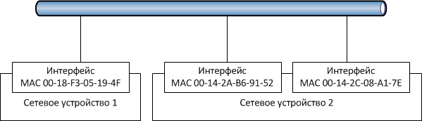
In the event that two or more adapters, having “listened” to the network, start transmitting data, collision (collision). Adapters, having detected a collision, stop data transmission, and then, having repeatedly “listened” to the network, repeat data transmission at different time intervals.
? NOTE.To receive a data packet that is designed for a specific adapter, it must accept all packets that appear on the network.
This method of access to the data transfer medium is called CSMA/ CD (carrier-sense multiple access / collision detection) - multiple access with carrier detection.
As follows from the above, with a large number of computers on the network and with intensive information exchange, the number of collisions grows very quickly, and, as a result, the network bandwidth decreases. It is not excluded the case when the bandwidth may fall to zero. But even in a network where the average load does not exceed the recommended (30-40% of the total bandwidth), the transmission rate is 70-80% of the nominal.
However, at present this problem has been practically solved, since devices have been developed that are capable of dividing the data flows between the computers for which this data is intended. In other words, traffic between ports connected to the sending and receiving network adapters is isolated from other ports and adapters. Such devices are called switches (switch).
There are various implementations of this technology - Ethernet, Fast Ethernet, Gigabit Ethernet, which can provide data rates of 10, 100 and 1000 Mbps, respectively.
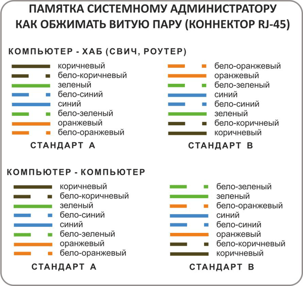
IEEE 802.3 contains several specifications, differing in topology and type of cable used. For example, 10 BASE-5 uses thick coaxial cable, 10 BASE-2 - thin, and 10 BASE-F, 10 BASE-FB, 10 BASE-FL and FOIRL use optical cable. The most popular specification is IEEEE 802.3 100BASE-TX, which uses unshielded twisted-pair cable with RJ-45 connectors for networking.
Ethernet network implementations
The Ethernet specifications listed above can be described as follows. The first number in the specification name indicates the maximum data transfer rate, for example, “10” indicates a signal transfer rate of 10 Mbps. “Base” means using the Baseband technology { baseband- this is a narrowband transmission). With this method of data transmission via cable, each data bit is encoded by a separate electric or light pulse, and the entire cable is used as one communication channel, i.e. simultaneous transmission of two signals is impossible.
Originally, the last section in the specification title was intended to display the maximum length of the cable segment (without hubs and switches) in hundreds of meters. However, for convenience and a more complete definition of the essence of the standard, the numbers in its name were replaced by the letters T and F, where T stands for twistedpair- twisted pair, and F stands for optical fiber.
Thus, it is now possible to meet networks based on the following specifications:
- 10Base-2 - 10 MHz Ethernet coaxial cable with a resistance of 50 Ohms, baseband. 10Base-2 is known as “thin Ethernet”;
- 10Base-5 - 10MHz Ethernet on a standard (thick) coaxial cable with a resistance of 50 Ohms, baseband;
- 10Base-T - 10MHz Ethernet over a twisted pair cable;
- 100 Base-TX - 100MHz Ethernet over a twisted pair cable.
A very significant advantage of various Ethernet options is mutual compatibility, which allows them to be used together on the same network, in some cases without even changing the existing cable system.
FULL DUPLEX MODE
The Fast Ethernet technology standard also includes recommendations for enabling full duplex operation (full— duplexmode) when the network adapter is connected to the switch or when the switches are directly connected to each other.
The essence of the full-duplex mode is the ability to simultaneously transmit and receive data on the Tx channels (channel from transmitter to receiver) and Rx (channel from receiver to transmitter), while the transmission speed doubles and reaches 200 Mbps. At the moment, almost all manufacturers of network equipment claim that their devices provide full-duplex operation, however, due to different interpretations of the standard, in particular, ways to control the flow of personnel, not. It is always possible to achieve the correct operation of these devices and good speed indicators.
FTTx technology from Rostelecom is one of the fastest and most reliable means for accessing the Internet. Such a connection is best suited for large companies that need a stable network connection to support digital telephony, send and receive large amounts of data, such as videotapes, as well as many other corporate tasks. The FTTx technology of Rostelecom is also not abandoned by individuals who wish to get maximum opportunities and enjoyment when using home boarding and interactive television, which is gaining increasing popularity recently.
FTTx technology Rostelecom - what is it?
FTTx is one of the most promising Internet technologies, which Rostelecom is developing very actively in large cities and beyond. The abbreviation stands for Fiber To The x, where x is any point, that is, your apartment, country house or office. In the Russian-speaking market, technology often has a simplified name "".
FTTx represents the general name of the technology range:
- FTTH (Fiber To The Home) - fiber optics connected directly to your house / apartment;
- FTTB (Fiber To The Building) - fiber comes to the building, and then distributed to apartments using other technologies (Ethernet);
- FTTN (Fiber to the Node) - the fiber optic signal is distributed on the network node.
- FTTD (Fiber to the desktop) - the signal goes directly to the network user’s room (it is also called FTTS, where the last letter stands for Subscriber or Russian subscriber).
What equipment do you need for FTTx Rostelecom
The Rostelecom provider in most cases installs FTTx equipment on nodes or in buildings, and then distributes the signal using switches over Ethernet technology. This option allows you to significantly reduce costs for the subscriber, but at the same time get a high connection speed. The FFTx line is capable of providing a capacity of several gigabits and thus can provide each of the home users with a stable connection with 100 Mbps. The positive side of this option in addition to high speed and low cost will also be the absence of the need to install special equipment in your apartment.
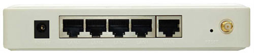
The subscriber will be able to easily start using the Internet by plugging the cord into network card computer, or using a router to distribute the connection to several devices. The choice of a router in this case must be made based on its speed characteristics and the planned number of network devices. If you have computers and set-top boxes (television or gaming) in your apartment that can be connected via an Ethernet cable, as well as devices using Wi-Fi technology, you will need to purchase a router with wired routing capability and an integrated wireless access point. Such a device will allow you to organize a convenient home network based on FTTx technology from Rostelecom without complicated configuration of the router and other equipment.
In cases where the fiber goes straight to your apartment (FTTH), you will need to purchase a special modem that will allow you to decode the signal and transmit it to the Ehernet output. Further, the setup scheme will remain the same. When you connect the fiber directly to the apartment, you can pay attention to the modems, which immediately act as the routers. This will free up space, getting rid of unnecessary network devices.
Setting up an Internet connection using FTTx technology
Depending on the type of FTTx, the connection setup from Rostelecom will be slightly different. In the case of FTTB, you only need to order the service from the provider and rent or buy a router suitable for you.
When used, you will also need to have a fiber optic modem to configure. Usually, when laying the cable, the provider’s employees themselves will install and configure the equipment. It will be difficult to connect without the help of a wizard to the fiber-optic network, if only because the crimping of the laid cables can be performed only with special equipment.
Thus, the setting of FTTx connections from Rostelecom will differ significantly depending on the subtype and of course the equipment used.
Attention! Fiber-optic modems have a very high cost, so when connecting FTTx to the Internet, the provider often offers equipment for rent or credit.
FTTx technology from Rostelecom is very new and promising. Its use is already actively conducted in large cities and beyond. Process of connecting to fiber internet may vary by technology subtype.
Today, the Internet services market offers many types of connections to the global network. Of these, three are the most popular: Ethernet, DOCSIS and FTTB. Each of them has features and advantages, which we will try to understand.
OnLime provider: Ethernet - from 290 rubles per month
Ethernet is perhaps the most common type of network in Russia. Computers of all users in one house, district or city are connected via a twisted pair, after which they communicate with each other at high speeds. It is convenient to share information - for example, games or videos. Providers can connect local networks to the global Web for optics, to improve speed performance.
The provider selects a point of presence in the territory through which it connects several buildings. At the point, a router is installed, then the individual home networks are connected to the fiber optic cable via a dedicated optical line. Switches are used for wiring around the house - they are installed in the entrances and a special cable is provided to each computer in the apartments.
Ethernet technology is used by the provider OnLaym - one of the leaders in the capital and the Moscow region by the number of new connections in recent months. A distinctive feature of OnLime is a wide choice of speeds and selection of individual conditions for each subscriber. Access speeds range from 30 to 100 Mbps, the connection is free, and the subscription fee starts from 290 rubles per month - very cheap, considering the average monthly rates in the country of 450-500 rubles.
Provider AKADO: DOCSIS develops speed
DOCSIS is a technology that connects to the Internet using television antenna. In it, bi-directional asymmetric channels are embedded in the structure of the cable network. Its most important advantage is that it is possible to deliver two services to the consumer via a single cable - Internet and television. Plus, high channel capacity and signal resistance to interference. Thus, the connection is obtained high-speed, multifunctional and inexpensive.
As the DOCSIS networks are upgraded, data transfer speeds increase - thus, in standard 3.0, the Internet access speed reaches 400 Mbit / s, the reverse channel - up to 200 Mbit / s.
If the Ethernet signal is distributed simultaneously to many subscribers, as a result of which the speed decreases, then in DOCSIS each client has a personal dedicated channel with a stable signal regardless of how many subscribers use the services of the operator.
DOCSIS technology, along with Ethernet, is widely used in Moscow by AKADO provider. Users communicate at 150 Mbps at a relatively small price. Subscription fee is only 399 rubles per month. Bonus package is free to connect and wi-Fi router, which AKADO provides to clients on a rental basis.
In addition, you can connect AKADO complex tariffs from the “fiery” line popular with Muscovites: “Iskra”, “Flash” or “Fire” for free. Each of them in the first quarter after connection costs 499 rubles per month, the speed range is from 60 to 150 Mbit / s, and the number of TV channels in the "figure" is 155 and higher. All this - with a Wi-Fi router and set-top box for rent.
Beeline provider: “super” tariffs and FTTB access
FTTB is an abbreviation of the term Fiber-to-the-Building, meaning fiber to the building. Internet comes through the fiber to the house of the subscriber, then passes to the apartment via a copper cable. This distribution allows you to best balance the high speeds. home internet and reasonable network installation costs. The initial investment for the provider may be higher than with the equipment of other types of networks, but they quickly pay for themselves. Users appreciate stable Internet, durable equipment and high speeds - the active growth of the subscriber base allows providers to set relatively low prices for access to the Web.
The benchmark for providing Internet using FTTB technology to the homes of residents of Moscow and the Moscow region is the provider Beeline. Modernization of networks has created a “margin of safety” for the provider, which makes it possible to offer customers not only speeds up to 100 Mbit / s, but also profitable complex services and equipment on preferential terms. For example, when connecting SuperGero packages, a subscriber receives, as a bonus for just 1 additional ruble, a functional wi-Fi router. And you can rent an HDD set-top box to TV packages that “can” record and rewind video directly from the air.
The rapid development of technologies allows each resident of Moscow and the Moscow region to choose a provider and conditions that best meet both the individual needs of the subscriber and his capabilities.