Power supply voltage of the hard disk. The procedure for connecting the hard drive to the computer. If information on the type of HDD interface is available.
Hello dear readers. Today, I'll raise an error whereby the inscription appears at the beginning of the windows boot
This error is due to incorrect connection of the hard disk. Therefore, proceeding from this I will tell you how to properly connect a SATA / IDE hard drive.
Proper connection of the hard disk.
The most common interfaces of modern hard drives are SATA, and for a slightly outdated interface IDE. SATA is more productive than the IDE.
The first step is to make sure that you are not going to damage any of your components with static electricity. If you have an antistatic wrist strap, attach it to the bare metal inside your case and attach it to your wrist. If you do not, the easiest way to stay free of static electricity is not to walk around while working on the computer, and often touch the bare metal casing to ground yourself.
Then remove the hard drive from the antistatic bag. You need to find somewhere to install it inside the case. Mechanical hard drives usually have a 5-inch form factor and are usually installed in the front of the case where the optical drives are located. They are fixed with screws or, in some more expensive computer cases, with snap-on brackets without tools.
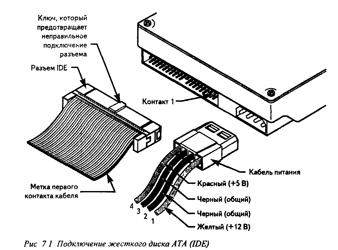
That's what IDE connectors look like ...
For each IDE controller, you can connect two devices. It can be HDD and CD / DVD drive, or two HDDs, or two CD / DVD drives. As a rule, controllers are designated as IDE0 and IDE1.
When connecting two disks, you must assign them priorities. In other words, you need to specify the master disk - master and the slave disk - slave to the system. ( sometimes they are denoted as device 0 - main and device 1 - slave). How are these priorities assigned? With the help of a jumper, jumper (in English jumper).
A 5-inch solid-state drive may not easily fit into the same slots. You can buy an adapter to convert a 5-inch bay to a 5-inch drive. Alternatively, you can often install a 5-inch drive in a 5-inch bay using only one or two of the four commonly used screws. This is not ideal, but since the solid state drive does not have moving parts, this is not a problem. We do not recommend doing the same if you have a 5-inch mechanical drive.
Once your drive is installed, and it will not go anywhere, you need to connect power and data. Connect it to the hard drive, then firmly press it so that it snaps securely. You may also need to connect this cable to the motherboard, where there will be a series of ports with the same shape. Otherwise, the performance may be limited.
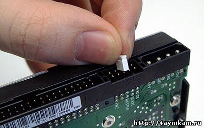
On the label HDD HDD as a rule manufacturers indicate how to put a jumper, so that the disc became the main or slave.
Devices to these connectors are connected via the IDE cable. There are 40 contacts and 80 contacts. By the connection mode, the cables are also Y-shaped. They work in cable select mode. On these loops there are three connectors - two on the end of the loop ( first master, second slave) and one in the middle. The central connector is connected to the system board, and the extreme connectors to the devices.
Once you are tuned, close your computer and start it. If not, your disk should appear on my computer with a new drive letter ready for use. Read this manual again before you start, so you know what this process entails. Then for some planning and construction tips that can ease your life when it's time to create.
Step One: Install the Motherboard

First open the box with the case, take out the case and open it. Usually this involves unscrewing a few screws with a thumb on the back of the case and removing the side panels. There must also be a bag of screws inside your case, take it now and set it aside, because we'll need it in a few minutes.
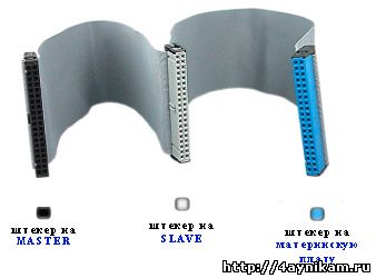
In this case, the edge connectors automatically assign a priority to the master to one device, and to another slave.
The operating system is installed on the main disk. If the drive on which the OS is installed is connected to the slave connector, the OS will not be loaded.
SATA interface
SATA connectors on the motherboard look like this.
You should see a rectangular space in the back of your enclosure where it should go. This requires considerable effort, so make sure that all four sides are securely fixed. You should see that the holes on the motherboard are aligned with the screw holes on the bottom of the case. There are probably more holes on your case than on your motherboard, so pay attention to what they are, and grab your opposing motherboards from the bag. Screw the racks into these holes and mount your motherboard over them.

Devices to the SATA connector are connected using a cord with plugs. On the plugs there are special "keys", guides, in the form of the letter "D" which do not allow to connect them incorrectly. To one SATA connector, unlike the IDE, you can connect only one device. The connectors are designated as SATA0 - the first, SATA1 - the second, SATA2 - the third, etc. Thus, in SATA, priorities are allocated between hard disks. In the BIOS, each connector can be manually set a priority. To do this, go to the Boot Sequence or Boot Device Priority section. This may be necessary in cases where automatic priority is not set correctly.
Now let's move on to solving the problem with an error no ide master h.d.d. detected press f1 to resume.
Step two: install the processor
Screw the screws of your motherboard into the racks so that the motherboard is tightly mounted. Open the processor unit and gently remove it. Your processor is one of the most fragile parts of the assembly, so this is one step where you want to be careful. Find the crown of your processor with the golden arrow on it, and then look at the processor socket on your motherboard for a similar turnout angle. Align these two arrows up, this is the direction in which your processor will enter the socket.
Error: no ide master h.d.d detected: press f1 to resume
This error occurs when the connection is incorrect HDD. This error indicates that the system does not have a HDD connected to the master connector. So HDD works in SLAVE mode, i.e. is connected to the SLAVE connector. It is necessary that, at least one HDD works in the mode master - Chief. The problem is solved by simply switching the HDD to an adjacent SATA connector, or if you have an ATA cable simply by switching the jumper to the master. That's all, perhaps.
Lift the lever to the processor socket and turn on the processor. Pull the lever down to lock it in place. Again, do it gently - it should not have any feats on your part, so if it does not get into place easily, something is wrong. Take it and try to reinstall it, make sure that your two arrows are aligned and, of course, double check that your motherboard and processor have the same type of socket.
After your processor connects, take the cooler that comes with your processor. It should already have some kind of silver thermal grease. Install the cooler on top of the processor. For more information about this, see the manual for your processor.
How should the right be made installing and connecting a hard drive.
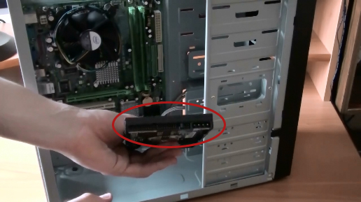
Where will we install it? In the case there are compartments for devices. The upper bays of the chassis are designed, as a rule, to install a CD / DVD drive. And the lower compartments, which are depicted in the picture, are designed to install the hard drive.
We choose any compartment and put the hard drive there. How will we dispose of it? It is necessary to place it so that the connectors of the hard drive are looking inside the case.
It can push a little, so do not worry about being too soft. For your video card, find the highest slot that fits your card, and match it to the plate on the back of the chassis. Then the card should sit on top of the socket, and all you have to do is press down to lock it in place. Screw the bracket to the body, and you're good to go.
Step Five: Install the Hard Drive
Note that if you need to remove it for any reason, there may be a small lever on the back of the connector that you need to press before pulling it out. Each case is slightly different from how they install hard drives. As a rule, there are two ways: in some cases you need to pull out the hard disk tray, insert the disk, secure it securely, and then reinsert the tray. Other motherboards just require that you slip onto a bare disk in the bay and then shove it into tight after the fact.

All. We inserted the disk, now it needs to be bolted. As you can see in the picture, there are corresponding mounting holes in the case.

For more detailed instructions on this particular step, refer to the manual of your case. If you use multiple hard drives and a large chassis, it is usually recommended to leave some space between them, that is, place them in the first and third bays instead of the first and second bays. This allows you to increase the flow of air between them and help them to work cold.
Step Six: Install the optical drive
The optical drive should be pretty straightforward. Just pull out the plastic cover on one of your 25-inch compartments and slide your optical drive. If necessary, replace it.
Step Seven: Install the Power Supply
This should be pretty obvious when your power source goes, as the back of your case will have a large rectangular hole. Some power sources are mounted from above, and some sit on the bottom of the case. As a rule, they are mounted with a fan facing away from the edge of the case, if only there is not enough space between the power supply holder and the end of the housing to provide airflow.It is necessary to ensure that the holes on the disk coincide with the holes in the housing. In them we will tighten the bolts.

How many bolts should be? It is desirable that there are four bolts. Two on one side and two on the other.
After screwing the disc on one side, turn the case and screw the other side.

What and where to connect
After you install it in place, you will see the holes on the back of the case with the screw holes in the power supply. Screw it into place and you will install it. Note. Many of you recommended installing the power supply before installing all the other items. Once again, think about before you build! This can be the most tedious and complex part of the process, depending on your case and power source. Separate the cords coming from your power source and connect them separately.
The 24-pin motherboard cable: this is the largest cable on the power supply, which gives the motherboard the electricity needed to run. You have a very long stub, as you guessed it, 24 small pins. Most cases should have a 20-pin connector with a 4-pin connector on one cable, so you can simply connect them and insert them into the large 24-pin connector on the motherboard. It must be fixed in place and can take a little effort to get it all the way.
We fixed the Winchester. Check that it does not move, if the disc is unsteady, then tighten the bolts stronger.

Installing the hard drive in the body is completed.
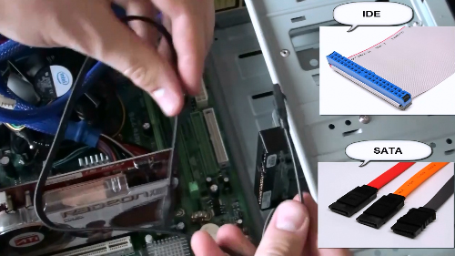
Connecting a SATA Hard Drive and an IDE
Now we'll figure out how to connect a hard drive with SATA and IDE interfaces . A hard disk can be connected to the motherboard using a narrow SATA cable or a wide IDE, which is shown in the figure.
The 4-pin motherboard cable: you must also have a separate 4-pin cable coming from your power source and a small 4-pin socket somewhere on the motherboard. These plugs are the same as the 24-pin cable - just press down until it locks into place.
Connect it to the end of the video card. Note that not all video cards require these cables, so if it does not have a socket, you can leave it. One of them is a skinny black plug coming out of your power source, which gives power to this drive.
Connecting a SATA hard drive.
If you have a hard drive connected using SATA interfaces, then we take this cable and connect one end to the hard drive, and the other to the corresponding connector on the motherboard.


Connect the power cable to the long pin on the hard drive and connect the data cable to the short contact. Repeat this process with the optical drive. It takes a little strength to get in, and even more strength to get out. All of them consist of only one or two contacts, and all are connected to the 8-pin connector somewhere on the motherboard. It depends on the build and build, so you'll need to check your motherboard's manual to see how they all connect.
Your motherboard may also have a small speaker that plugs into the 8-pin connector that you find on your motherboard and will be listed in the manual of your motherboard. When you do all this, you want to be careful when you put these cables. As a rule, you want to keep them as good as possible. The more they get confused in the middle of your business, the more they are going to block the flow of air from your fans, forcing your computer to work more hotly, louder and maybe even overheat.
We have a hard drive with SATA interface.

Connecting an IDE Hard Drive
In the connection of the disk, using the IDE cable, there are special features. The color end of the cable, in our cases blue (as a rule it's the longest), must be connected to the motherboard.

Your case may have come with some postal links to help you wrap them and take them out of the way. In some cases, there are even built-in cable management functions, such as clamps or holes, through which you route these cables to prevent them.
Cable management is a beast for one's own, and it differs from case to case, so it's just something you'll have to face. When you're done, plug the power cord back in, turn on the power switch, and press the power button on the front of the chassis.
The other two ends marked in the figure are connected either to the hard drive or to the CD / DVD drive.

The peculiarity of the IDE is that on one cable, you can connect two devices.

Important! If we connect two devices to one cable, then one of the devices must be priority.
There are two modes:
- Master -this device is connected to the IDE cable closest to the system board. MASTER it is recommended that you connect the primary hard disk with the operating system.
- Slave This is a device on the som remote connector from the system board. SLAVE(not the main thing) it is recommended to connect a CD / DVD drive or another one, not the main second hard disk

Note that there is a key on the plug. (highlighted in the picture)

And in the connector on the motherboard, there is also a turn-key. It is necessary that these protrusions coincide.

We insert the cable into the connector and press it lightly from above to fix it securely on the board.

The cable is connected. Now we need to connect it to the hard disk.
We take the cable and in accordance with the keys (on the cable there is a key and on the hard disk) we insert it into the disk.

Attention!
In a particular case, it may be necessary to independently set the mode (Master or Slave) for each of the IDE devices using a jumper on this device.

That's all. The hard disk is installed and connected, I hope you succeeded.